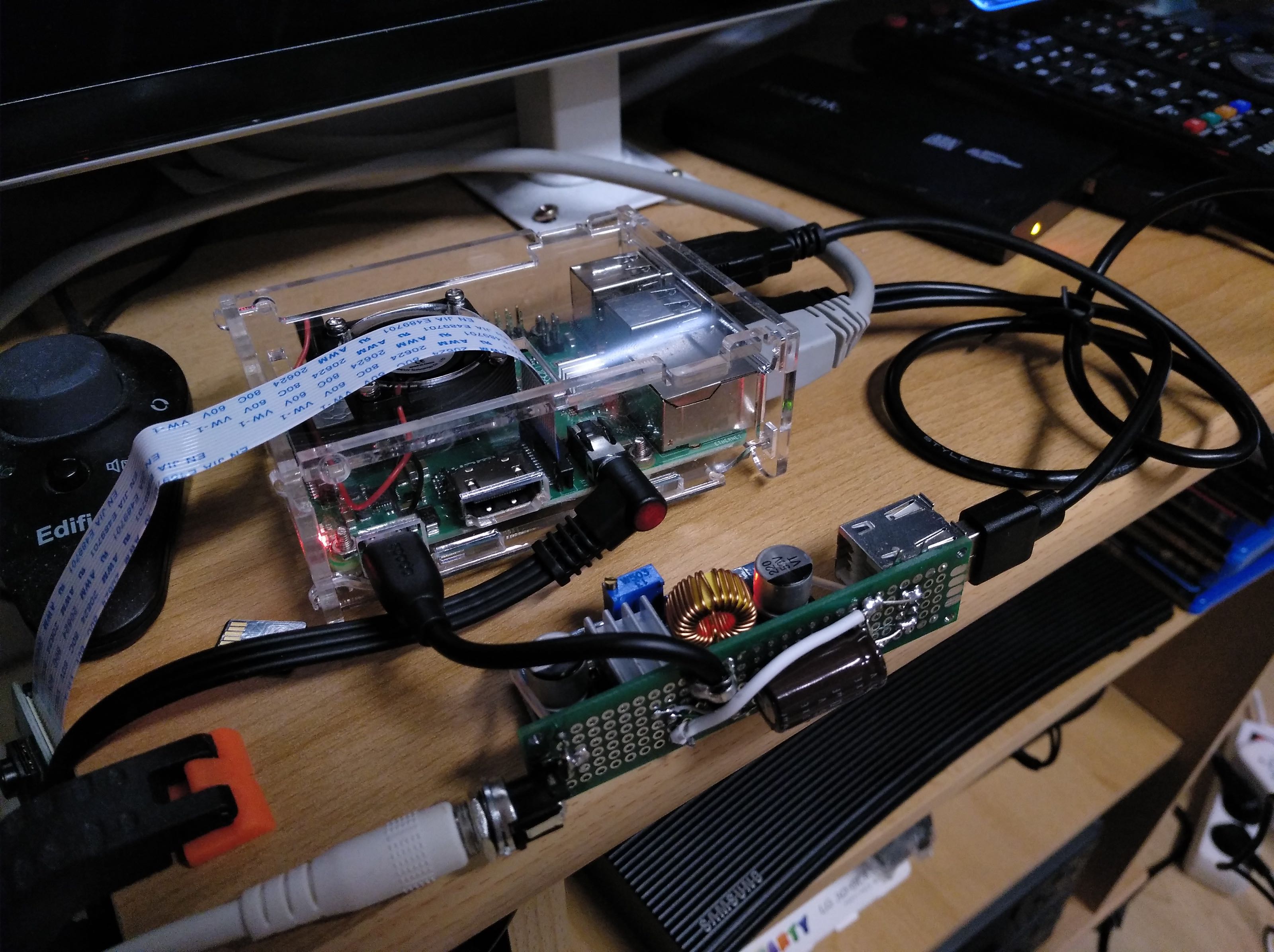
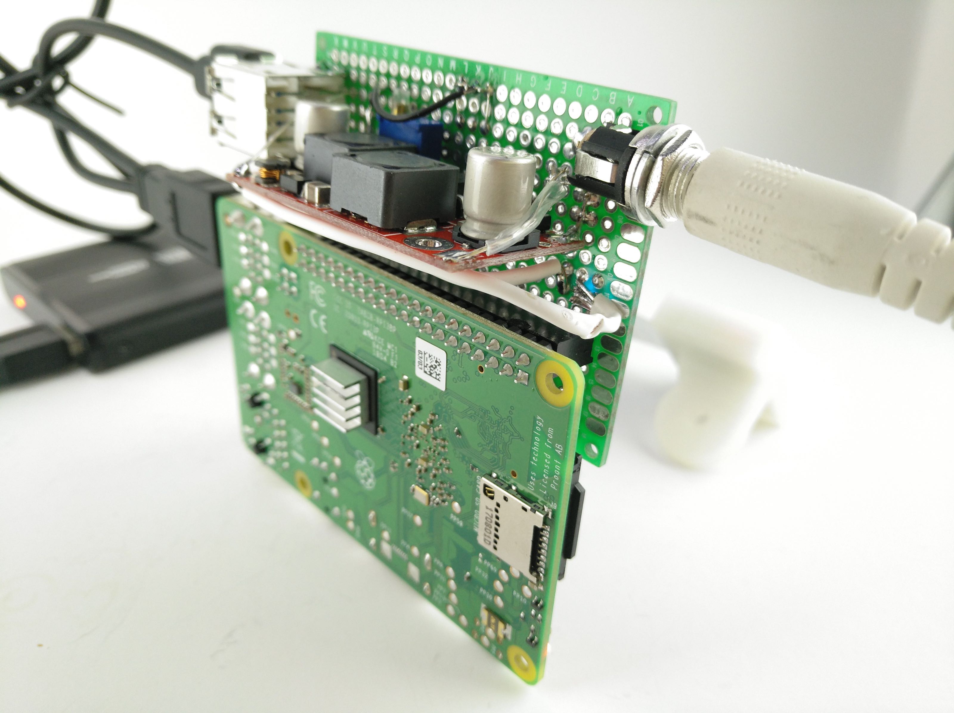
Don’t you hate that "Undervoltage" out of the blue? I've had one too many USB hard disk lockdowns on my Pi today, so I decided to solder-hack a new power supply with an efficient adjustable step-down converter and enough oomph to not be bothered by sudden spikes in demand. Instead of 5 volts, this one’s ready to accept anything from 6 to 30 volts on the input. With only a short cable to the micro USB in, an extra buffer capacitor and two additional USB power-only sockets, now I can run my USB-boot SSD without piping its current through the Pi’s USB ports). I set the voltage level to 5.1 volts and the Pi hasn’t had a hiccup since.
The circuitry is quite simple, and the parts were sub-10 € in total:
- Switching power supply for 220 V AC to 12V 2.5 A DC, 2.95 €
- Adjustable buck converter XL4015 max. 30V/5A, 1.30 €
- 12V connector 5.5 / 2.1 mm, 0.35 €
- MicroUSB charge cable (to cut apart), 1 €
- USB socket "dual layer female A", solderable, 0.15 €
- piece of perfboard 2x8cm, 0.20 € in bulk or 2 € solo ...
- some wire and shrink wrap, < 1 €
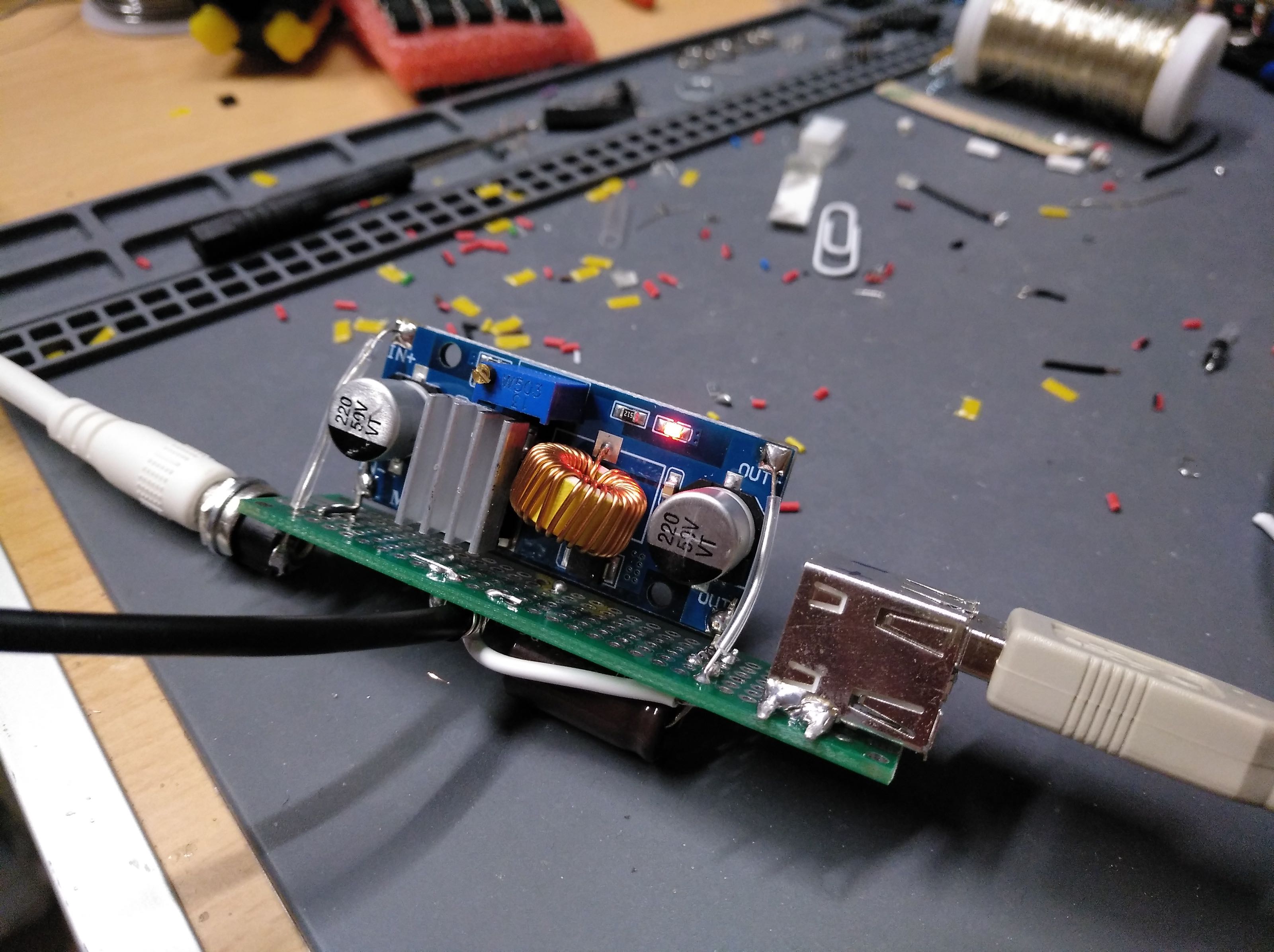
Using two leftover 1/10" 90° pins, I soldered the negative pads of the regulator perpendicular to the perfboard, then added the 12V connector on one end and the USB socket on the other. The buffer capacitor sits on the other side of the perfboard, mainly because it didn’t fit anywhere else. I soldered the output of the regulator to the red (+) and black (-) wires (or, for this cable, (-) to the unisolated ground bundle) of the microUSB plug, and to the power lines of the USB socket.
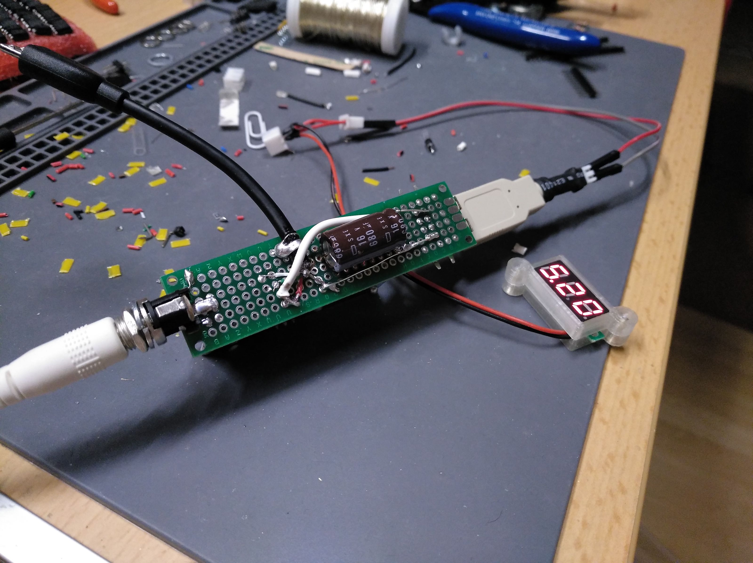
DO NOT connect the raspberry and the USB SSD until you've adjusted the output level to 5 volts. Most of these modules come with a "random" output, which may be as high as the raw input voltage, and will fry your Pi. Use the potentiometer to adjust the output to 5.1 volts - this may require a lot of turns counter-clockwise (YMMV) because there's a tiny worm screw gear inside. (If it starts clicking against the end stop and the output still hasn’t decreased, you’ve been turning it the wrong way.)
Once that’s sorted out, you can plug in your Raspberry Pi and extra storage and it won’t go down easily (the regulator has built-in short-circuit, over-temp and over-current protection). Even though the supply I used offers "only" 2.5 amps, the nice thing is that it's incoming at 12 volts (12 V x 2.5 A = 30 watts), and buck regulators do not burn off the extra voltage as heat like linear regulators do, but rather they "trickle" short bursts of electrons through the coil, then smooth that out into a regulated lower-voltage steady stream. So you can pull 4 amps at 5 volts (20 Watts) at the output with no problem (if the wires are up to it). 
No more timelapses filling up the SD card, either  Now I just need to make an enclosure so I can mount it to my printer …
3 Likes
I like it. I think I would have designed a hat with a fan that cools both the Pi's CPU and the cooling fins on that power board at the same time, bringing the power down to the Pi via the GPIO pins. You'd then power the hat, it does its thing and then powers the Pi. I suppose you could then add a 4-digit 7-segment display to indicate the power.
I've had it running for quite a while now; the main source of heat is actually the freewheeling diode of the secondary coil while the driver IC is barely warmer than environment. The MOSFET switch has barely any resistance while the 0.6 V forward voltage drop of the diode can’t be avoided.
The enclosure of my pi doesn’t have room for a hat, and for that regulator I just went with the modules I had at hand. There are also some with built-in displays, but once the output is set it’s not really necessary (though I'm not averse to LED bling  )
)
Not that you need to fix anything... It's been a while since I've analyzed circuits but what we would do a long time ago is just to source a second identically-rated diode and solder that in series (making sure that both diodes' sides touch). In theory, then, each uses half the current as before and less than half the heat each.
Honestly, just bypass the pi's onboard regulator, it's total garbage. Put a properly regulated 5v straight into the GPIO pins (make sure it IS properly regulated lest thee suffer pi death)
Sorry, what regulator?:
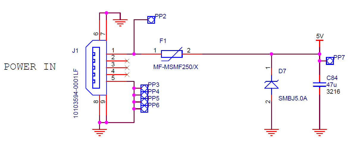
The only thing that is bypassed is the PTC Resettable Fuse. Even the 5V z-diode (actually it is a 9.2V Clamp 65.3A Ipp Tvs Diode) will work that way.
1 Like
I'm using a 3b+, which is supposed to have a different schematic, but so far I've only considered the 3.3v /1.8v side of things that runs off a buck converter on the newer models.
Adafruit did publish this more complex schematic in an older article:
https://learn.adafruit.com/assets/17934
This still doesn't do much for the 5 volt stability though
I've had another pi run an openCV compile task over night (didn't finish successfully because I'm not good at following instructions  ) and though the load varied quite a bit from "all cores" to "all swap", the internal undervoltage event counter had nothing to report after 12 hours. Same goes for my OctoPi (the undervoltage check, not the compile fail) - no more flashing lightnings in Octoprint! So I'm happy with my Frankensteined PSUs
1 Like
I've take this from the official RasPi 3B+ schematic: https://www.raspberrypi.org/documentation/hardware/raspberrypi/schematics/rpi_SCH_3bplus_1p0_reduced.pdf
The one you referred to is from the RasPi 3B: https://www.raspberrypi.org/documentation/hardware/raspberrypi/schematics/rpi_SCH_3b_1p2_reduced.pdf and former boards. And this not a regulator, it's a protection circuit.
If you want to go secure, you could inject your 5V into PP1/PP2 or solder it directly to pin 1 of the USB connector.
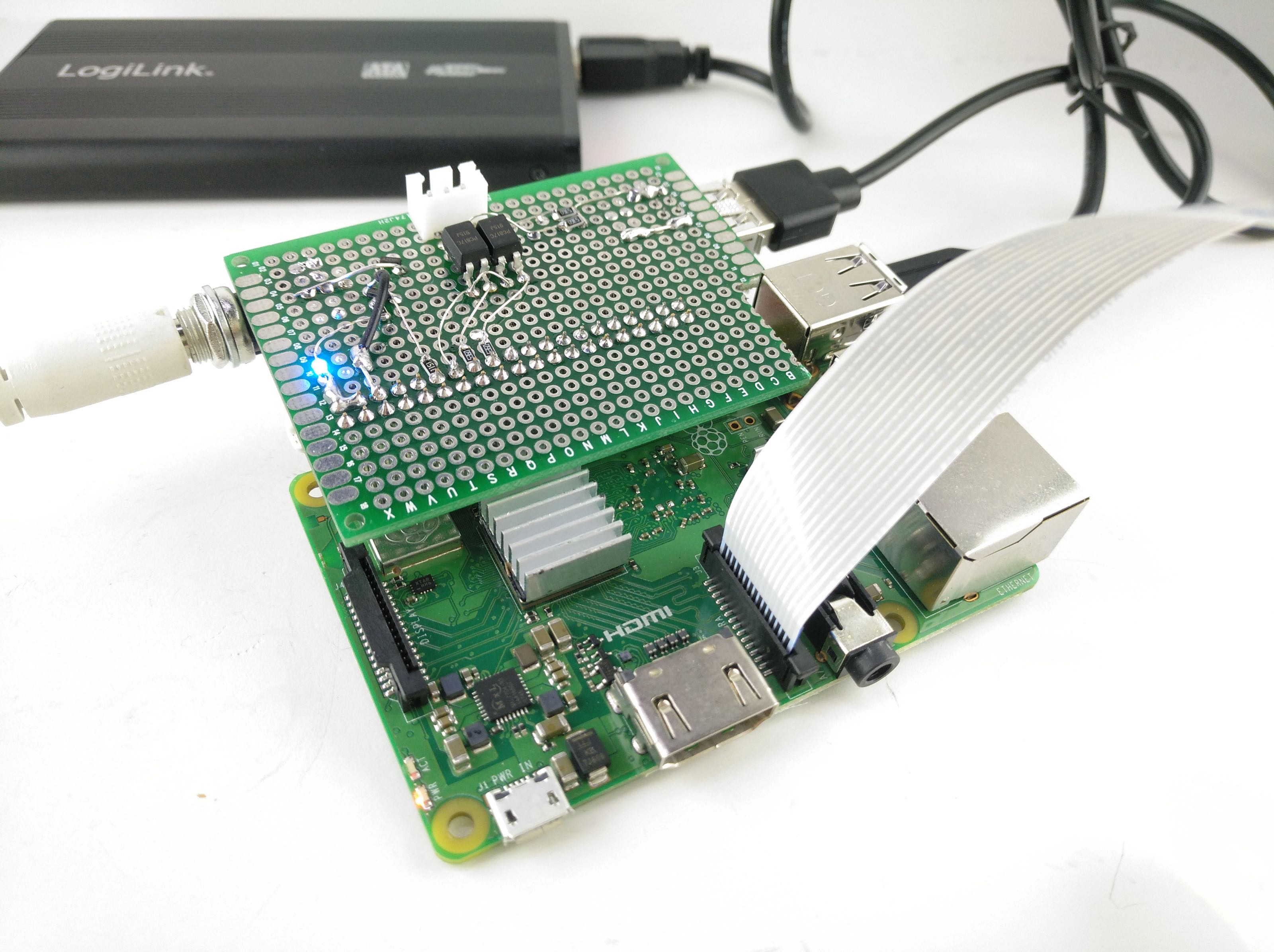
That’s an idea; especially since I've already added a tiny "hat" (more like "a piece of perfboard with two connectors, soldered to a 2x20 socket") a few weeks ago to my OctoPi that connects a shutdown button and a SPI output for a dot matrix display. I'll try to add another JST-XH there for 5V in (and convenience ).
Just as a followup: "mark 2" of the Unflinching Pi Power Supply, now with a XL6009 buck-boost module (running out of XL4015 buckys, I need to order some again). Plugs into the GPIO, also adds two inputs with optocouplers and an output with a pull-down mosfet. Not exactly meant for my OctoPi this time, though since it works quite well I'll take that as a blueprint for the next one (which I'd like to add a stepper driver to, so the OctoPi can slowly move its camera module on a track for timelapses by correlating the progress value with a 0-100% position range)
2 Likes