I am using a raspberry pi and the power supply that came with my wanhao i3
Hello did you solve the problem with relay? I have de same issue and I don´t have more ideas to tray it.
Hi R1dd1ck913,
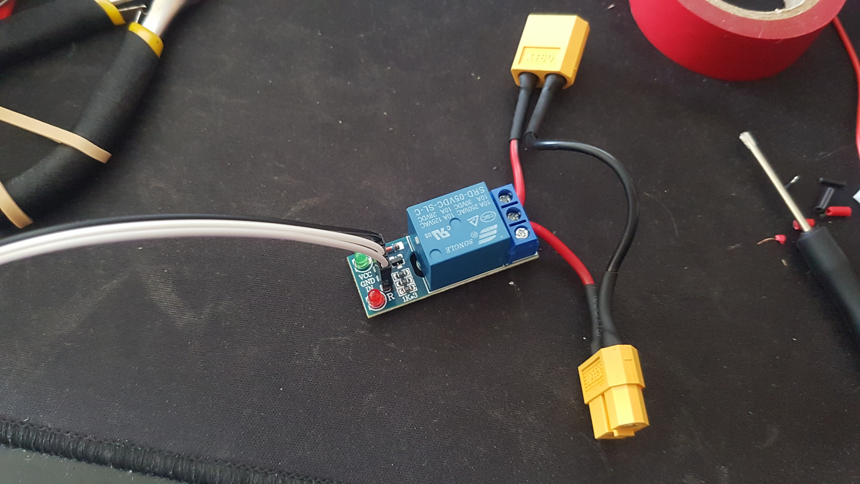
I am wondering what you mean by "GPIO (board)", Is that the relay board ? The relay board according to the picture has VCC, GND and IN, how did you hook them up to your R-Pi ?
First thing would be to have it working on the plain command line I guess.
Regards
Jan P.
This guy solved the issue with a transistor and resistor. I can confirm this works.
Thank you. Sorry to say I'm glad some one else had the same problem as me. Thanks for the link I will order some parts and try this out.
I realise this is an old post but i just want to give an alternate solution to this issue.
There are 2 issues at play here. The first is the relay's input is inverted meaning in order to turn it on the input pin must be pulled low. This alone isnt an issue because PSU Control has an option to invert the control signal. But because its a 5v relay that also means the input pin must be allowed to reach 5v in order for the relay to switch off.
And theres the second issue. The PI is a 3.3v device so as soon as a GPIO pin is set to output mode it is oulled down to 3.3 volts which seems to be enough to activate the relay.
My solution is to simply put a string of 3 diodes in series on the control line. Each diode has a voltage drop of 0.5 volts. This allows the control relay's input pin to reach 4.8 volts (3.3 + 1.5) when the GPIO pin is high. Thats high enough to turn the relay off.
This does also mean the relay input pin can only be pulled down to 1.5 volts when the GPIO pin is low but we already know thats more than low enough to turn the relay on.
tbh i probably would have just used the transistor solution if i had bothered to properly read this thread but i missed the solution and so went and figured out my own solution. The only real advantage my solution has is it can be easily spliced into your existing signal wire without needing an additional board.
1 Like
In a situation like this I will first insert a large heatshrink (3" long) up on the insulated wire. Next, I will add a smaller heatshrink section (1" long) which will eventually cover all those naked diodes. You then shrink the smaller one over the diodes, bring in the bigger one and shrink it down over all the wires.
I had the same issue, and it took some time to figure it all out.
What I had : sometimes it worked just fine, sometimes there was no 'click' when the command was sent to switch the relay back to normal position (which means that the Pi is sending a low command). It was like 'low' was not low enough.
So, long story short : switching a relay DIRECTLY from the Pi's GPIO pins is NOT a good idea.
And indeed, when I switched the relay by hitting the ground contact, it really did switch. So there must have been some voltage still left, not 'low' enough to switch it.
After some digging, I found out that -in order to properly switch a relay- you need to add a transistor or opto coupler first, they make 'low' really 0 (and no voltage left), so the relay really switches nicely.
This is a very simple but very effective design (credits to the original author) : https://gpailler.github.io/2018-03-02-octoprint-psucontrol/
1 Like
Hello,
I'm having the same problem but there is something I don't understand, why do I need the extra circuits when the videos on YouTube have a direct connection to the Raspberry Pi? Its because it's a diferent relay? Should I buy a diferent relay? I'm not confirtable doing the custom circuit...
Photo of my relay attached and I'm using Raspberry Pi 3 B+
Thanks.
Hello,
Wasant he talking about the transistor, in my case, already included in the relay board?
I was talking about the extra circuit just to make it work since I have the same problem. After setting the pin number on PSU Control and save the relay activates and stays always On... Previous comments are suggesting diodes or transistors to solve the problem. I was talking about those extra circuits.
Thanks
brandon's reply a little later suggests that there are two issues: inversion and the 3.3V data logic versus a 5V relay.
1 Like
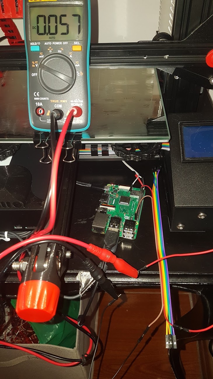
ok, i was testing and I think I did understand the problem, even if I dont have enough knowledge to solve it. From my testing my relay signal has around 4.5v and my raspbery pi switch between 0v and 3.3v... the relay should not have any voltage or it should be 3.3v?
If I could buy a 3.3v relay from ebay it should work?
thanks!
Not that I've done this particular project but it sounds like brandon was suggesting a reversal of the logic. In theory, anything less than 2.5V then would not trigger the relay. Anything above that would trigger the relay (to include the Raspi's 3.3V high logic level). At least that's my take on what he wrote. But this might require checking some box in the plugin's setup.
Perhaps opening a dialog on the plugin author's repository might help.
so, after some search about "raspberry pi relay" I could find this video : https://www.youtube.com/watch?v=My1BDB1ei0E
as he said on the video i test the relay with 3.3v in the VCC instead of the 5v and... it works!
for others with the same problem and probably the same relay from ebay try to use the 3.3v pin instead of the 5v from the RP.
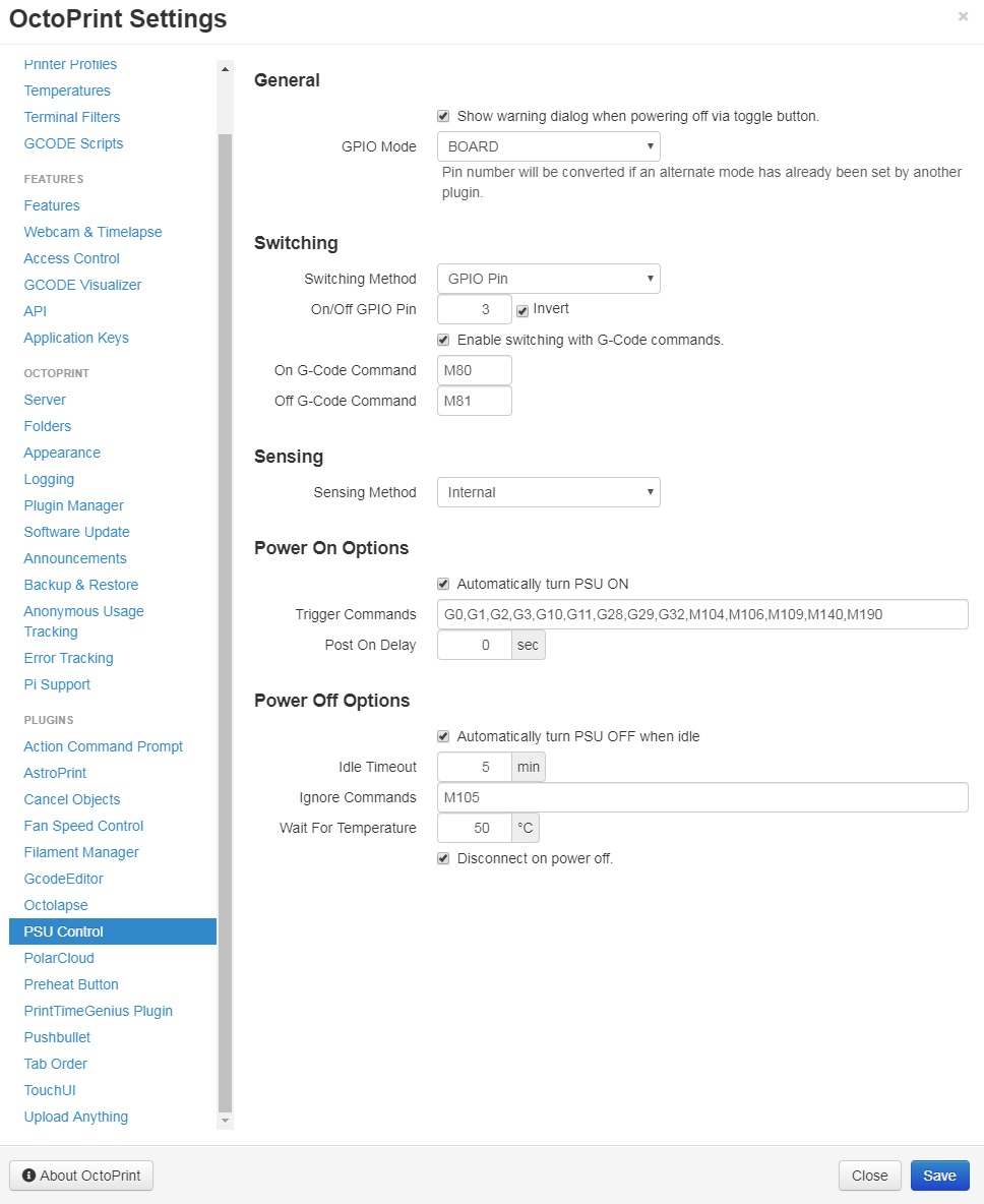
My PSU Control settings for reference (i used pin 3 INVERTED for signal, pin 1 (instead of 4) for VCC and pin 6 for ground) :
3 Likes
Thx this helped me <3
Just a little conclusion for me. If the relay doesnt switch i have two options
- modify the relay board to work with RPI 3.3V GPIO pins https://github.com/foosel/OctoPrint/wiki/Controlling-a-relay-board-from-your-RPi
or
2.Solder the circuit with the transistor and the resistor like shown here, https://gpailler.github.io/2018-03-02-octoprint-psucontrol/ (better and safer)
is this right?
I Solder the solution from gpailler, the relay is switching, i hear it clicking but the Energy didnt switch. Any Troubleshootings
I had same issue spent about 4 hrs trying, but after I saw this post and Transistor I checked signal wire from GPO 21 which is the pin I am using and ON voltage is 3.3 volts and OFF voltage is 0 volts when relay is disconnected, so is working so maybe relay is causing feedback so will try the transistor mod later ..
John
directly connecting a relay to GPIO is a bad thing that is very bad and will probably kill that GPIO pin, and if you're really unlucky, nuke the entire pi
why, I hear you ask?
a) the relay probably draws more current than the GPIO pin can provide
b) if it does succeed in driving the relay, switching the relay off will cause the magnetic field in its coil to collapse. this generates a massive voltage spike back to the GPIO pin. so you MUST connect a diode across the relay to absorb the spike
relay drivers have all this circuitry so really, very really, use one
HTH YMMV