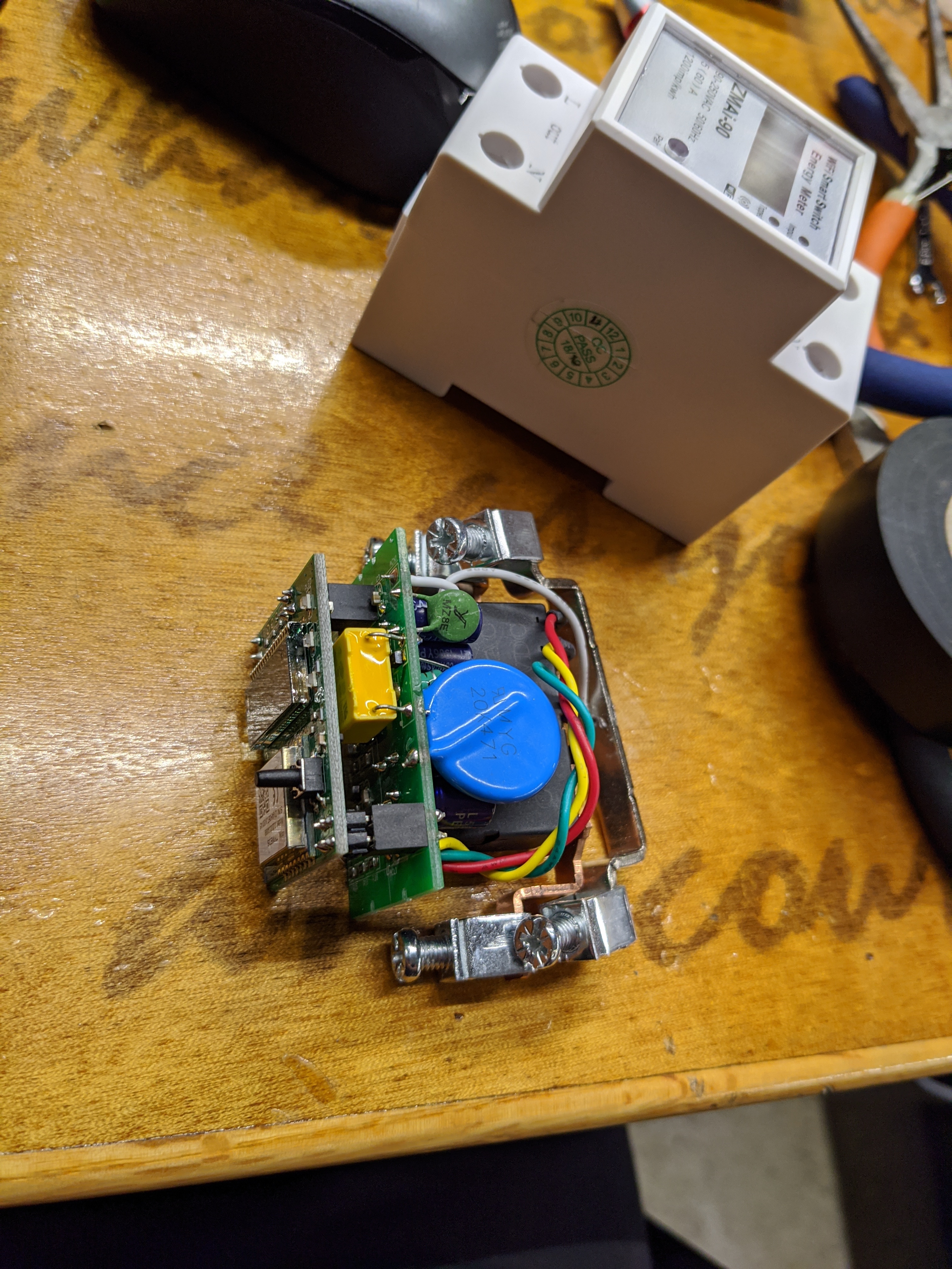
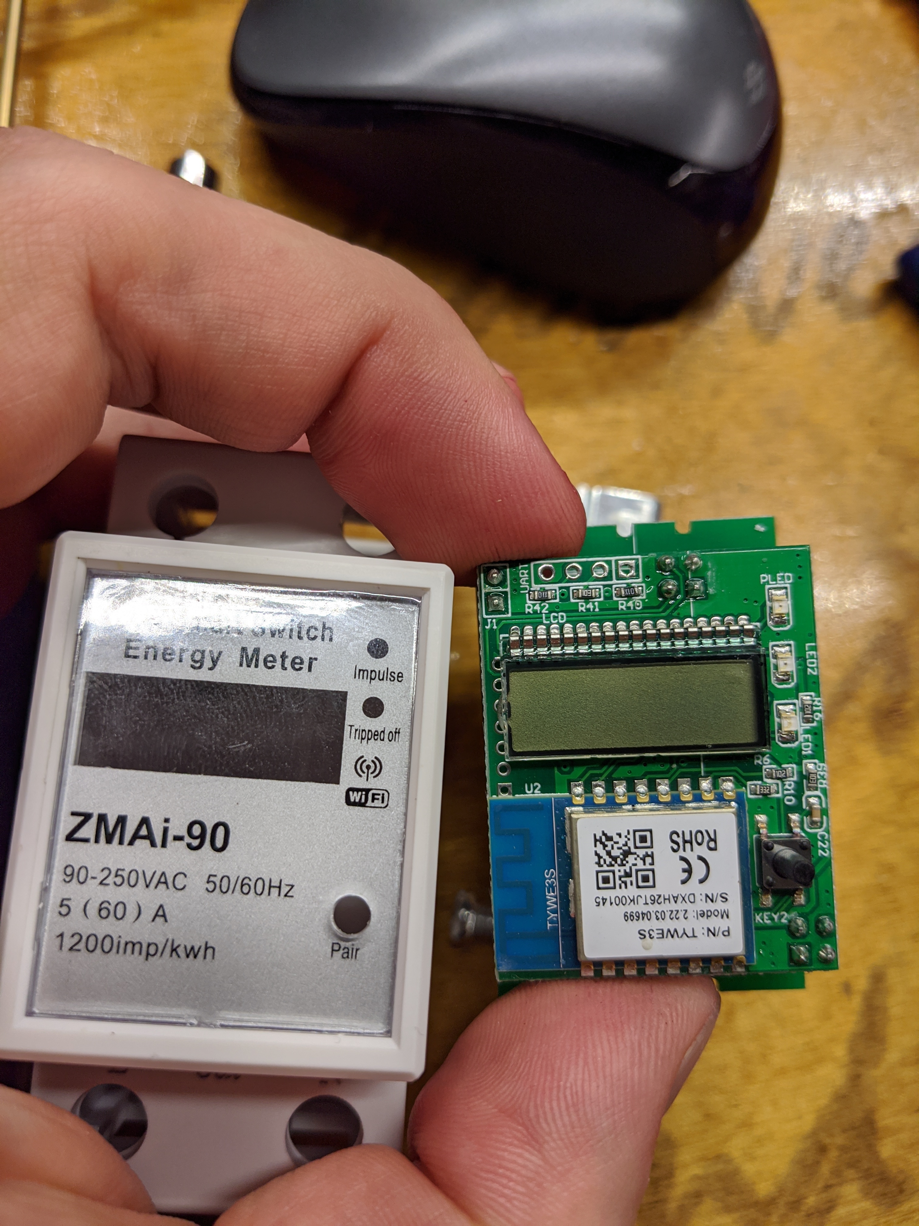
I have found a low cost AC intelligent power meter: ZMAi-90
There are separate apps to read this data through wifi, but how awesome would it be to see it in Octoprint? This would also allow tracking power used for an AC Heated bed and compute the real cost of a print. This is the first request. The power meter has a UART capability supposedly, here is some initial work on that.
Also a request I may ask of the creators of temperature failsafe, PSU control, and the Enclosure plugins is to have a redundant thermistor in the hotend that the RPi can directly read through an ADC. It is possible in Marlin to have a redundant temp sensor, but then you are still relying on the control board to function and report the temperature back to Octoprint. If the RPi could independently make this decision, it would be a whole new level of safety. Then if the hotend is overheating, you can use PSU control to shut off the PSU. Some of the temp sensors for the enclosure plugin could work for the bed, but it may be easier to use a normal thermistor for that as well.
The next request is much more involved, but I think would increase the safety of 3D printing greatly.
So the overall idea is to use the ZMAi-90 via UART to track AC input power and set up Volt/Watt meter on the DC side. In this way the PSU performance can be monitored and failure could be detected much earlier. I have a 5V PSU running the RPi, and the RPi then controls a relay module to turn on a 24V PSU. If you measured DC volts/amps from each power supply, you could subtract the DC power of each from the other and compare to AC power measured and then detect failure in each PSU or the RPi itself and also potential failure in the relay module. Then you could monitor TMC 2209 or other TMC driver debug info to determine if friction is up or there is some problem with movement, hotend/bed temps and heatup times through the control board and through the RPi, fan speeds, printing jerk/accel/speeds, ambient temp, print speeds, basically any parameter that can be measured. Then use AI like the spaghetti detective is using for imagery to detect any significant changes. If failure is detected Octoprint can command to cancel the print using a mini ups like the BTT UPS 24V V1.0 Module to cancel print and resume later.
One issue is that you can’t kill power to the 5v PSU, because the Arduino relay module relays are either normally open or normally closed. If you wire it as normally closed, then when you hit the power switch the RPi turns on, but if you use the RPi to kill its own power, the relay will reset and turn the PSU back on. Wired the other way the relay wont close with the power switch to turn on the 5v PSU and RPi. An AC based relay could possibly be used. Killing the 24V PSU would be the biggest concern as far as fire or other major failures are concerned though.
And for a little more cost you could get a TP-Link smartplug with energy monitoring and get graphs and stuff with my plugin (which will eventually make it's way into my tasmota plugins).
If you don't mind doing me a favor and going to the web console and typing Status 8 and posting back the response, that would be awesome. I don't have a device with energy capabilities up at the moment.
[Blush] Thanks Gina, that will help with further development. Any idea what the unit of measure is on those numbers? Or what apparentpower and reactivepower are?
Those smart plugs could potentially work too. I like the idea of communicating via uart between the switch and pi though, then you are not dependent on your WiFi network to be functioning for failure detection, I'm assuming comms don't go directly between the pi and smart switch.
The main thing that drew me to the zmai-90 is that I can use solid copper wire inside the enclosure to wire everything up and nothing is external. The zmai-90 also seems to do some filtering and conditioning of the input power. I could of course make everything internal with a smart plug but then there are more connectors or fancy soldering. The zmai-90 also displays some info on it's screen but that may not be that useful.
I just purchased a 2 pack of the sonoff POW R2 devices from Amazon and will be getting it Monday. Look forward to putting it together and adding the energy logging. Looking at the reference on the Tasmonta site it seems that the serial interface is unusable once configured for energy monitoring because it uses up that connection.
Note - After the module type is changed to “Sonoff Pow R2”, the serial port is no longer available for entering configuration commands because the serial port is used to communicate to the power measurement chip.
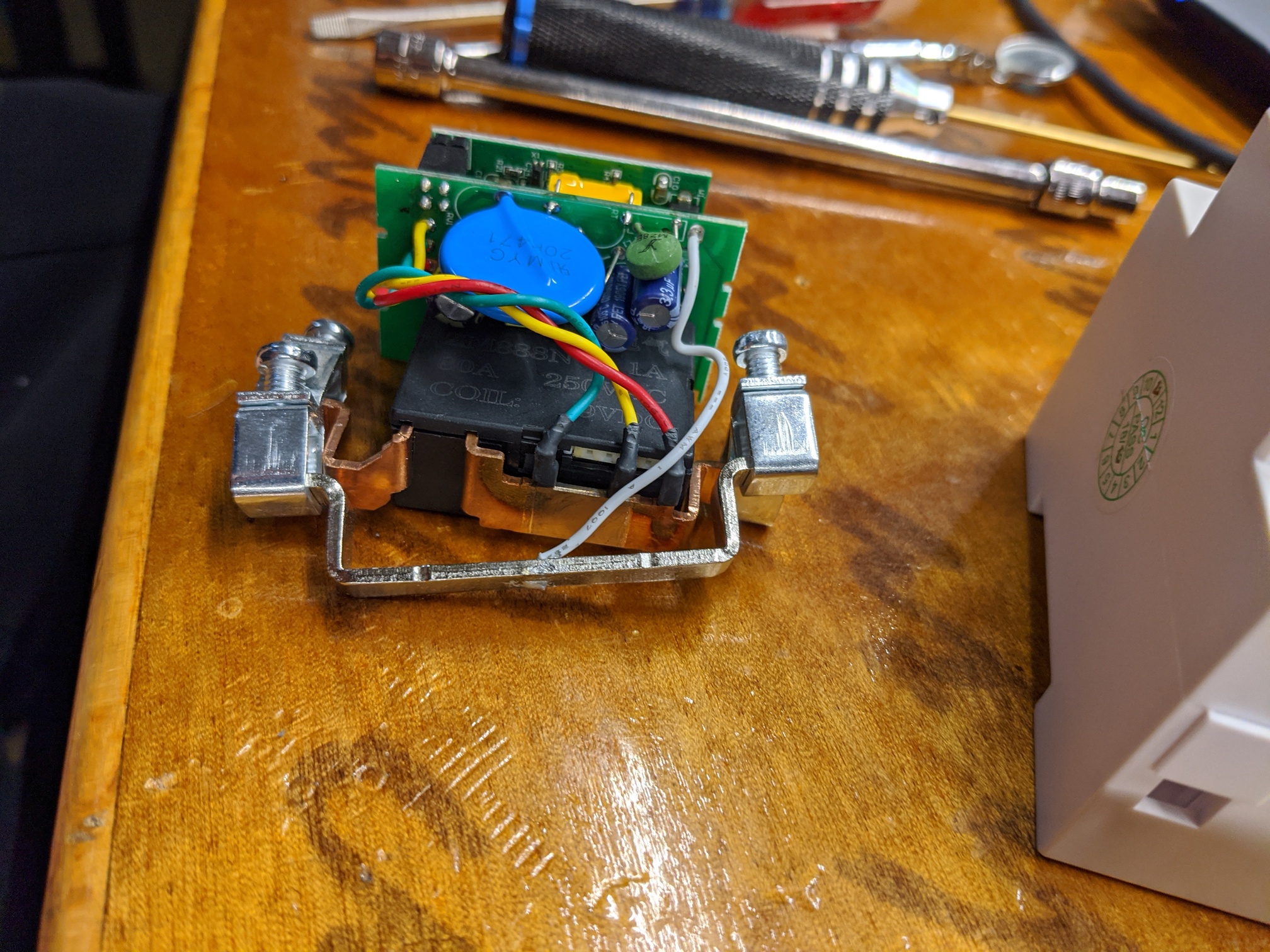
Here are some pictures of the inside of the ZMAi-90. The UART connection is open to be soldered to right above the LCD.
From the ali link above, this bullet is interesting. It seems like the switch does some filtering:
"With active energy pulse output for calibration, it is a passive photoelectric isolation type OC gate output port with a pulse width of 80ms ± 20ms; the waveform is square wave."
Too bad it does not have a rail for the ground to act like a ground fault switch as well.