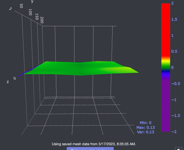
we've had our Ender 3 v2 (w/ a cr touch) for about 2 weeks and getting used to it. i think i have the leveling pretty dialed in and setup the cr touch auto leveling how it should be (i think). Prints seem to work pretty well. I setup bed visualizer tonight and i'm not too familiar w/ it yet but it looks pretty drastic so not sure how to read it. how can it seem so level and prints work and it look like this? is this normal or what would this tell me?
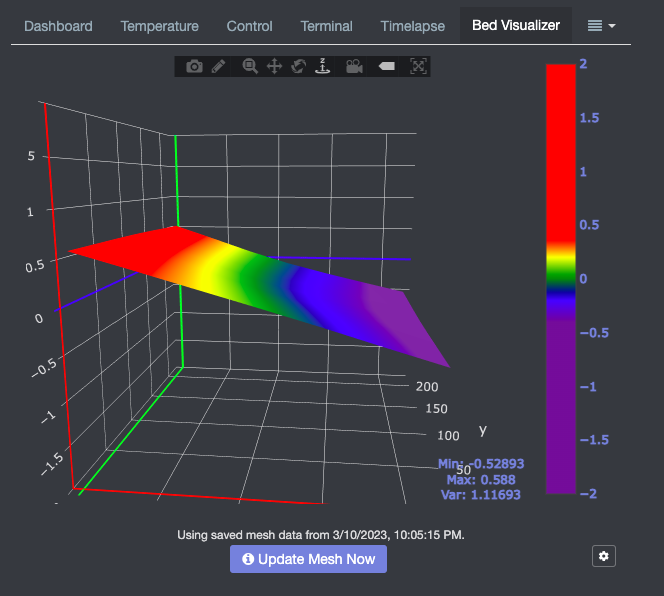
The probed distances difference that you are seeing is relative to the frame. Things like single lead screws and cantilevered x axis like what's on the Ender 3 can cause drastic droop like that. The whole point of the CR Touch is to compensate for that lean, but adjusting the screws to minimize that would be ideal. Typically recommend trying to get the variance (Var:) to within a layer height.
thanks for the help here! so i found that the wheel on the right side of the z axis was loose and measuring from the top bar down to the Z, the left side was 1/16th inch higher on one side compared to the right to start so i got that fixed up tonight. where else were you suggesting i check/adjust? i'm going to re-manual level tomorrow and see how it goes. and on that topic, as we're still learning correct me if i'm wrong but this is the process we're following:
- Manual level (w/ paper / adjusting screws on each corner)
- Auto home
- Set Z offset at auto home location so paper is just starting to rub on the paper (not sure if doing this at home location is critical or not but what i've done)
- Run Leveling from the panel
Your steps 1-4 are correct as a good process.
thanks! outside of adjusting the z axis bar so its level to the top bar like i did, is there anywhere else i should look at adjusting to help w/ that drastic angle or that just a known limitation of this level of printer? i do understand that the cr touch is meant to compensate for it all. just wanted to make sure i tuned up as much as i could so the motors didnt have to act as hard to compensate if possible
typically the screw adjustments under the bed are where you go after adjusting the left/right height to be "square" to the frame. that is where you get most of the physical adjustment in getting the bed trammed. You may want to check out the AutoBim plugin for that.
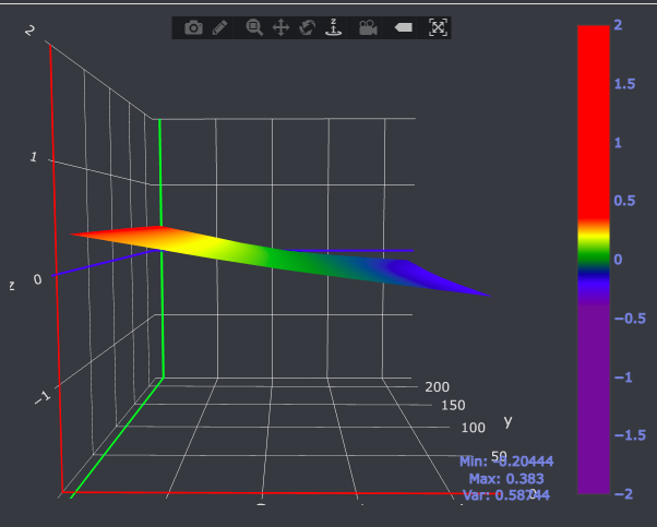
cool thanks! thats what i was thinking but just making sure there wasn't another part of the axis or frame you were referring to. i've done the starting all the way down method and tried to keep them even as i could but w/ the paper trick i always end up needing some to be cranked up more so far. BUT i did get the Z axis to be level (measuring from the top bar) all the way across and this is my updated visualization. (variance down to .58 from 1.1) so a decent improvement. I was looking a little into the autobim as well and that looks awesome! i need to figure out if i need a different firmware on my 3 v2 to use it yet
You might want to consider measuring from the base rails of the frame instead of the top. Something like this could help, with accompanying video.
https://www.printables.com/model/186044-ender-3-x-gantry-alignment-tool
oh nice thats super helpful! thanks for the tip!
as for the bed leveling i am very interested in autobim. have you used it on a v2 by chance or no?
I have not used it, but pretty sure it's straightforward. The only thing on the firmware side is that it supports the G30 command.
I'd recommend reading the plugin's GitHub readme.
thanks for your help here! i'm gonna see if my GD-Ender-3 V2-Marlin2.0.8.2-HW-V4.2.2-SW-V1.0.7_E_N_BLTouch firmware works w/ Autobim tomorrow to start. the part I can't wrap my head around yet is if i have my gantry level to the bottom bars (printed those guards you suggested today...great idea there!), and i move all my adjustment wheels all the way down (to start at the same starting point) why do i keep ending up needing a couple of the corners to be way cranked one 1 way and others always need to be the opposite. bed warping maybe? i may be overthinking it
Could be the bracket that holds the bed, could be the bed warped, or could be the way the wheels are aligned on the rail. Your not necessarily overthinking it, but there's too many variables to say it's just this one thing. That is one of the reasons auto bed leveling/tramming even exists.
thats fair.....i had thought about the brackets or warming be (fully knowing this is a budget printer) and right, one of the main reasons we got the CR touch. and when i've manual leveled i usually start by lowering them all the way and then give the all 6-7 full turns (trying to be consistent) so i have enough wiggle room for the one that ends up needing to be lower. pretty interested in the autobim to see if it helps simplify. hopefully the marlin firmware that i have supports it (looks like its the most current one on creallitys site
do you happen to know if Autobim is still useful if i have mriscoc firmware that has a bed tramming wizard?
probably not if it's the auto bed tramming that uses the probe. the plugin is basically mimicking what that option in Marlin does with the LEVEL_CORNERS_USE_PROBE