Really need to see the response from your G33 command in order to help better. The serial log just shows the commands being sent. Honestly, this is something that I haven't tweaked much.
Serial Log contains these lines:
2019-04-24 23:23:59,527 - Recv: Z-probe:11.826 X:169.00 Y:5.00
2019-04-24 23:24:00,604 - Recv: Info:Distortion correction matrix:
2019-04-24 23:24:00,606 - Recv: -465, -441, -125
2019-04-24 23:24:00,611 - Recv: -597, -806, -564
2019-04-24 23:24:00,615 - Recv: 1500, -1367, -965
2019-04-24 23:24:00,617 - Recv: G33 X-12.00 Y5.00 Z0.352
2019-04-24 23:24:00,626 - Recv: G33 X-12.00 Y97.50 Z-0.140
2019-04-24 23:24:00,631 - Recv: G33 X-12.00 Y190.00 Z-0.109
2019-04-24 23:24:00,636 - Recv: G33 X78.50 Y5.00 Z-0.320
2019-04-24 23:24:00,642 - Recv: G33 X78.50 Y97.50 Z-0.189
2019-04-24 23:24:00,647 - Recv: G33 X78.50 Y190.00 Z-0.103
2019-04-24 23:24:00,652 - Recv: G33 X169.00 Y5.00 Z-0.226
2019-04-24 23:24:00,657 - Recv: G33 X169.00 Y97.50 Z-0.132
2019-04-24 23:24:00,663 - Recv: G33 X169.00 Y190.00 Z-0.
Are not they what plugin expects as printer response? Attached serial.log contains 4 such blocks corresponding to screenshots from my previous post.
Thanks
Weird, not sure why my previous download of that file wasn't showing, now it is. I'll take a look. Really instead of 2 flip options I need a rotate option. The programming of that may be complicated, which is why I probably went with flipping the data as it's just reversing the array elements versus transposing them.
@jneilliii Why do you even need flip options? Aren't you parsing the actual X and Y values from the received distortion correction matrix?
While the extract from serial.log in my previous post is result of executing G33 command, the order in which the lines with XYZ values appear in the printout follows the probe movement as for G32 command. As I mentioned in my original post these movements are different. Not sure if this matters, just decided to bring it to your attention.
One other thing that may be unusual in my case - X coordinates (probe location) of few first measurement points are negative. Repetier calculates them as X value at measured point plus the X offset between probe and the nozzle. The same for Y. In my printer offsets are: X_offset = -24.500, Y_offset = -13.5mm. If the plugin does not expect negative values, this may be causing problem.
Being new user of your plugin, I found it difficult to understand whether Flip options will just change the chart appearance, or affect the way printer output will be interpreted the next time G33 is run. Looks like it is the latter case. Would be nice to have more detailed description of this functionality in the documentation.
Should you need any additional data to be collected or tests to be run in case you update the code - I'm ready to assist.
Thanks for the great plugin and outstanding support you provide to all its users!!
Actually, no. I developed this under a Marlin UBL format response and therefore the matrix is reported quite differently than how Repetier reports. The positions of the x/y probe points are not the actual points, but an interpreted position of the overall bed size divided by the number of probe points in that axis. I know it's convoluted but was how the plugin developed.
And to be honest the Repetier support was added by someone else as a pull request and since I don't have a device with that on it I have no way of testing.
The problem is - there is no common standard between firmware developers on how the output of G33 needs to be formatted.
Anyway, I just fixed the issue by swapping 2 lines in Distortion.cpp file of Repetier.
These lines
void Distortion::showMatrix() {
    for(int ix = 0; ix < DISTORTION_CORRECTION_POINTS; ix++) {
        for(int iy = 0; iy < DISTORTION_CORRECTION_POINTS; iy++) {
need to be replaced with these:
void Distortion::showMatrix() {
    for(int iy = 0; iy < DISTORTION_CORRECTION_POINTS; iy++) {
        for(int ix = 0; ix < DISTORTION_CORRECTION_POINTS; ix++) {
And again, since there is no single standard, it is unclear whether this needs to be fixed in Repetier, or in the plugin. I will report this to Repetier developer here Let's see what will he decide.
Thanks for your support! I am all set for now. Just curious how comes I ended up being the 1st who discovered and reported this issue 
Or any of the output generated by pretty much all of the commands. Welcome to my hell.
It might be worthwhile to open an issue on Repetier's repository and suggest this as a feature request, stating the reason.
I've reported this issue to Repetier developer in this thread and he makes valid point:
I think the plugin should test the positions, that is why we write them down.
I will look into plugin code this weekend and try to find out if it is possible to extract and use actual X and Y values from firmware printout rather then expecting it to appear in certain order.
"You can not expect all firmwares to behave the same..."
I dunno. That statement feels a bit like a cop-out to me. All firmwares should reasonably try to behave the same with respect to its communications to the outside world.
If I were to start creating a new firmware, I would attempt to make it like the existing Marlin externally and then try to make it better internally in what it does. And then I might try to add new features outside of the core behavior which add value to the user.
So after looking into the code that was added to my plugin by someone else to support repetier the plugin is actually swapping the axes here the same way I was for older marlin formats. I think that is incorrect and will be looking to rectify maybe this weekend. The only problem is, does repetier report differently between versions the way marlin does, or maybe this is an issue also in the older marlin format, I just don't know.
Based on this article distortion correction functionality (G33) was added to Repetier 0.92.8 on 03/01/2016. I am running version 1.0.3 and the output (before I swapped 2 loops in Repetier code) looked like in my earlier post in this thread.
Hopefully someone owning a printer with older Repetier firmware after reading this thread will be willing to share extract of the log with output of G33, or will just confirm that the format did not change.
Thanks
I've posed the question to @gztproject at the pull request linked below, which is what introduced the Repetier firmware support. Hopefully he can help.
Hi all,
unfortunately soon after my pull request I had to change a motherboard on my printer and I switched to Marlin, so at the moment I don't have access to a Repetier machine.
What I did was just add the format (G33 Xxx.xx Yyy.yy Zzz.zz) as reported by the Repetier G33 L0 command (originally it would ignore the line).
As I remember it worked fine so I didn't dig deeper. Let me try to find some time over the weekend, test it on a friend's machine and see what's happening
Thanks @gztproject.
@lmcbmai, if you go into OctoPrint's logging settings and set the octoprint.plugins.bedlevelvisualizer to debug logging and then run through a leveling process using the plugin's button. The octoprint.log should add some additional information to help debug this issue. I'm pretty sure I know what's happening, but want to verify first.
Ok, I've done some debugging with the virtual printer and faking the response from the 2 variations of firmware responses. This is what is happening within the plugin.
classic marlin:
[['40.00', '20.00', '7.31'], ['80.00', '20.00', '7.38'], ['120.00', '20.00', '7.35'], ['120.00', '70.00', '7.37'], ['80.00', '70.00', '7.41'], ['40.00', '70.00', '7.35'], ['40.00', '120.00', '7.33'], ['80.00', '120.00', '7.36'], ['120.00', '120.00', '7.34']]

becomes:
[['40.00' '80.00' '120.00' '120.00' '80.00' '40.00' '40.00' '80.00' '120.00']
 ['20.00' '20.00' '20.00' '70.00' '70.00' '70.00' '120.00' '120.00' '120.00']
 ['7.31' '7.38' '7.35' '7.37' '7.41' '7.35' '7.33' '7.36' '7.34']]

repetier:
[['-12.00', '5.00', '-0.075'], ['-12.00', '97.50', '0.084'], ['-12.00', '190.00', '0.994'], ['78.50', '5.00', '-0.075'], ['78.50', '97.50', '0.060'], ['78.50', '190.00', '0.134'], ['169.00', '5.00', '-0.002'], ['169.00', '97.50', '0.106'], ['169.00', '190.00', '0.193']]

becomes:
[['-12.00' '-12.00' '-12.00' '78.50' '78.50' '78.50' '169.00' '169.00' '169.00']
 ['5.00' '97.50' '190.00' '5.00' '97.50' '190.00' '5.00' '97.50' '190.00']
 ['-0.075' '0.084' '0.994' '-0.075' '0.060' '0.134' '-0.002' '0.106' '0.193']]
As @lmcbmai mentioned it's completely because of the order in which the probe points are queried/reported. Old marlin report seems to go back and forth within the rows/column while repetier performs a diagonal move between each row/column.
I think the easiest approach to resolve this would be to apply a 2 dimensional sort on the array prior to processing. That way the input array will always be in the same format. Now I have to figure out how to do that. I'm not really that familiar with numpy, so I'll be doing some searching.
.
I may have a solution now. Through the use of some multi-dimensional sorting and a final flip of the z positions I think it is reporting correctly now. My tests with old marlin formats and @lmcbmai's newer repetier format seem to be working properly. The x/y positions on the surface are still just a division of the overall bed dimensions and not the actual x/y coordinates supplied by the reporting due to firmware differences. It should give you an idea of how your bed is leaning though for sure. If you guys don't mind doing some testing by installing the plugin using the url below in plugin manager that would be great. Want to get some feedback before I go live with the updated version.
https://github.com/jneilliii/OctoPrint-BedLevelVisualizer/archive/repetier_test.zip
Recv: Info:Distortion correction matrix:
Recv: 4241, 573, 824
Recv: 359, 258, 452
Recv: -322, -321, -10
Recv: G33 X-12.00 Y5.00 Z-0.075
Recv: G33 X-12.00 Y97.50 Z0.084
Recv: G33 X-12.00 Y190.00 Z0.994
Recv: G33 X78.50 Y5.00 Z-0.075
Recv: G33 X78.50 Y97.50 Z0.060
Recv: G33 X78.50 Y190.00 Z0.134
Recv: G33 X169.00 Y5.00 Z-0.002
Recv: G33 X169.00 Y97.50 Z0.106
Recv: T:26.34 /0 B:60.04 /60 B@:0 @:0 T0:26.34 /0 @0:0 T1:-20.00 /0 @1:0
becomes

@jneilliii Hi, thanks for looking into this and trying to address the issue. I run few tests this morning. Here is the detailed description of what I did:
- Uninstalled old version of plugin and installed repetier_test.zip
- Checked plugin configuration - all my settings were still there. I have only "Save mesh" checkbox selected.
- Reverted back the change I made to Repetier firmware (see post #7 above)
- Run 4 tests with business card placed on one of the bed corners
- Test 1 card at Xmin/Ymin corner
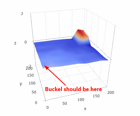
- Test 2 card at Xmax/Ymin corner
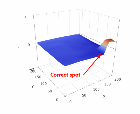
- Test 3 card at Xmin/Ymax corner
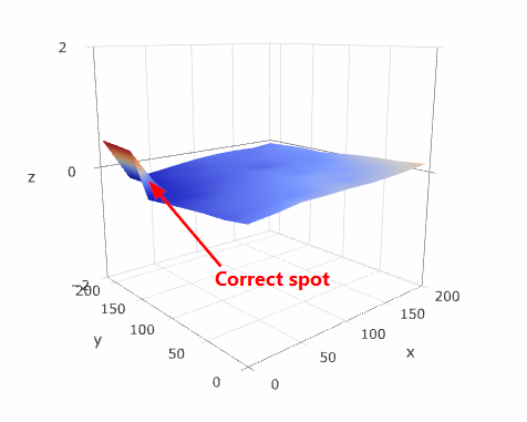
- Test 4 card at Xmax/Ymax corner
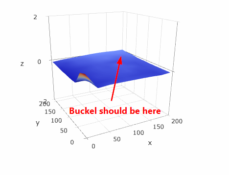
Each test run the sequence of commands listed in my 1st post here. G32 had 5x5 grid and G33 had 9x9 grid.
As shown on screen shots, we still have the same issue, however the chart is now flipped along Xmax/Ymix to Xmin/Ymax line. Initially it was flipped along Xmin/Ymin to Xmax/Ymax line.
Log files are attached.
Repetier_Test1.zip (53.0 KB)
Thanks
Assuming your screenshots are in order of the description of where you have put the card, those graphs are right. Xmin/Ymin position is always loaded as being the point closest to you unless you have the center option enabled (for deltas). Did you flip your screenshots around for Test 1 and Test 4?
I am sorry, I uploaded all 4 screenshots together and the order got messed up. I just updated my previous post and corrected the order.