Could this become a plugin?

One year later, back to business. Very few will be interested, but the most important is having fun !

The shield/hat (THT components only, easy to populate) :

The PSU controller, with a bistable relay (draws zero power when power is off) :

The encoder and the two needed buttons (printer + emulator reset, Marlin didplay on the HDMI monitor) :

The code still needs some polishing, and I'm struggling with the PSU Control pluggin (can't get it to recognize what happens on GPIO17...)

2 Likes

Pretty nifty, don't forget to change the plugin's name...

Yes, these relays are great. But they have two drawbacks :

  • not easy to source from Amazon or eBay
  • the way I use it (in a loop including the PSU), they require two contacts, one being on the live wire (see Mötley Crüe - Live Wire (Official Music Video) - YouTube) ; this means using an indutrial grade push button and a minimal knowledge about electrical safety/routing/cable management. As far as I rememenber, PCs don't have a real power button for such reasons since the rise of the ATX PSU...

This schematics shows the high voltage wiring. The other contact (circuit not on this schematics) is hooked to the hat/shield in order to pole short and long presses.

[EDIT] forgot to say : they also don't draw any power while active...

I uploaded the project to GitHub ; it is unfinished, but functionnal :

Hostly, I'm bit scared of this:

grafik

The distances between high and low voltage connectors are way to low for a conventional push-button. And the few millimeters between the open contacts inside the stitch can't be enough. Exception is when you use some fancy expensive stuff.

Of course not a small button for electronics.
It's an industrial button mounted with two contacts, rated 250V/10A(Ith) ; Schneider Telemecanique ZBE series. Not the most recent, but I have tons of them. Same contacts you will find on machine tool commands.
The distance on a schematics has no relations with the button physical properties ; the reference is not on the schematics.

[EDIT] datasheet : https://www.se.com/ww/en/product/download-pdf/ZBE101

DSC_8478
DSC_8474

1 Like

Phew, I feel much better now :+1: :blush:

Another way to do this ; I made this a couple years ago for a RasPi enclosure with it's own tiny SMPSU ; 250V 5A contacts, with a good isolation between the Faston connectors (the red thingy near the end is an LED that is used as a power indicator) ; made with "natural" PETG ; works and looks great !

22mm indusdrial buttons are hard to push, and it is there for testing only. Their contacts can be used as shown on the picture and are very smooth ; I plan to dedicate a section of the enclosure to the high voltage (IEC socket, fuse holder, main rocker switch, PSU, bed SSR), and the other one to the low voltage (RasPi, hat, motherboard), with a separation and one contact in each section, actuated with a double pushrod instead of a single one.

1 Like

Some news : a short demo of the emulator.
The PSU management is to be redesigned from ground up...

1 Like

Some news.

First, I dropped (for now) the power management, as having a Marlin UI plugin that manages the PSU makes no sense at all !

Repository reorganization :

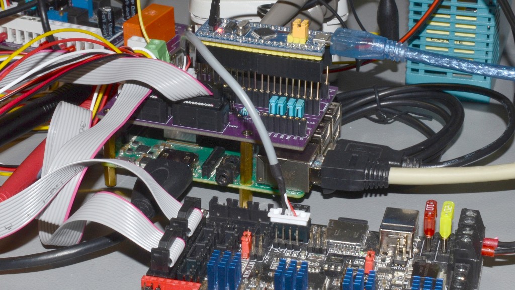
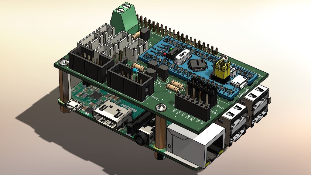
PCBs and firmware : GitHub - yet-another-average-joe/MarlinOctoHat
Plugin : GitHub - yet-another-average-joe/OctoPrint_MarlinOSD_Plugin
Service : GitHub - yet-another-average-joe/OctoPrint_MarlinOSD_Service

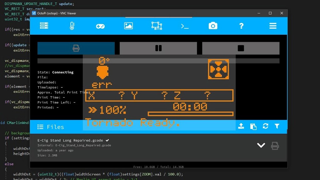
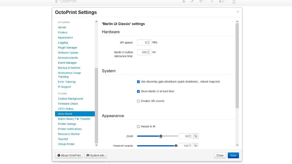
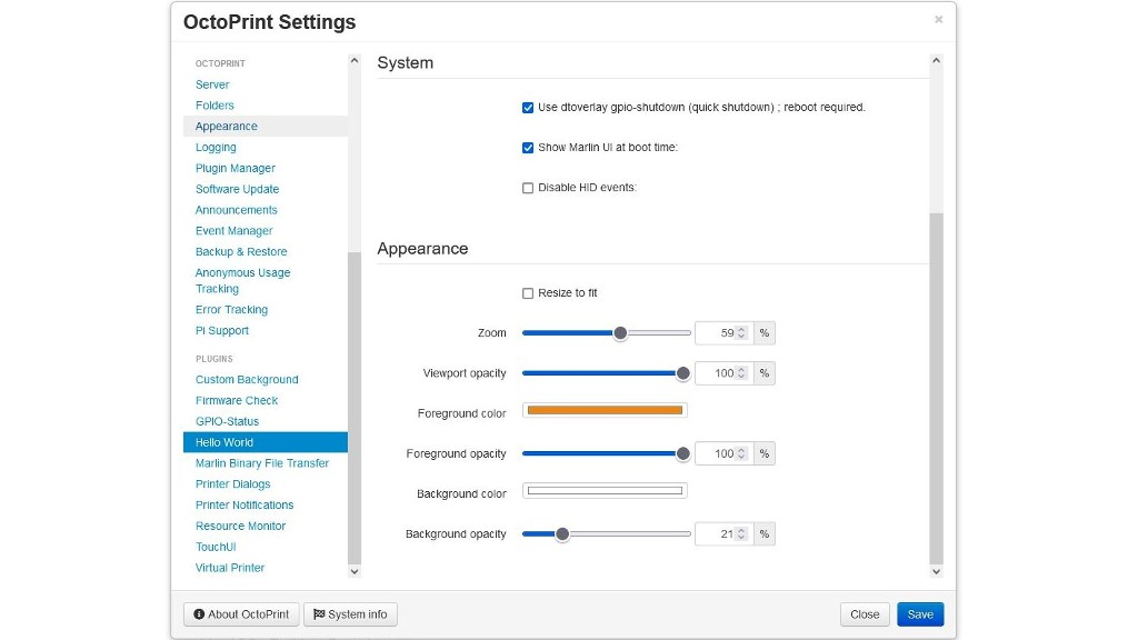
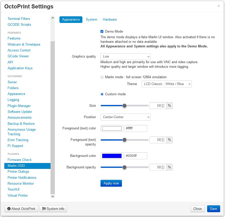
Also, it is now possible to have a preview, and play with the Marlin UI appearance without electronics ; the demo mode is activated by default, and will display the typical blinking 12864 LCD. It is also displayed if something goes wrong with SPI (never happened, except after removing the BluePill form it's socket !)

Of course, the service has to be compiled and installed first !

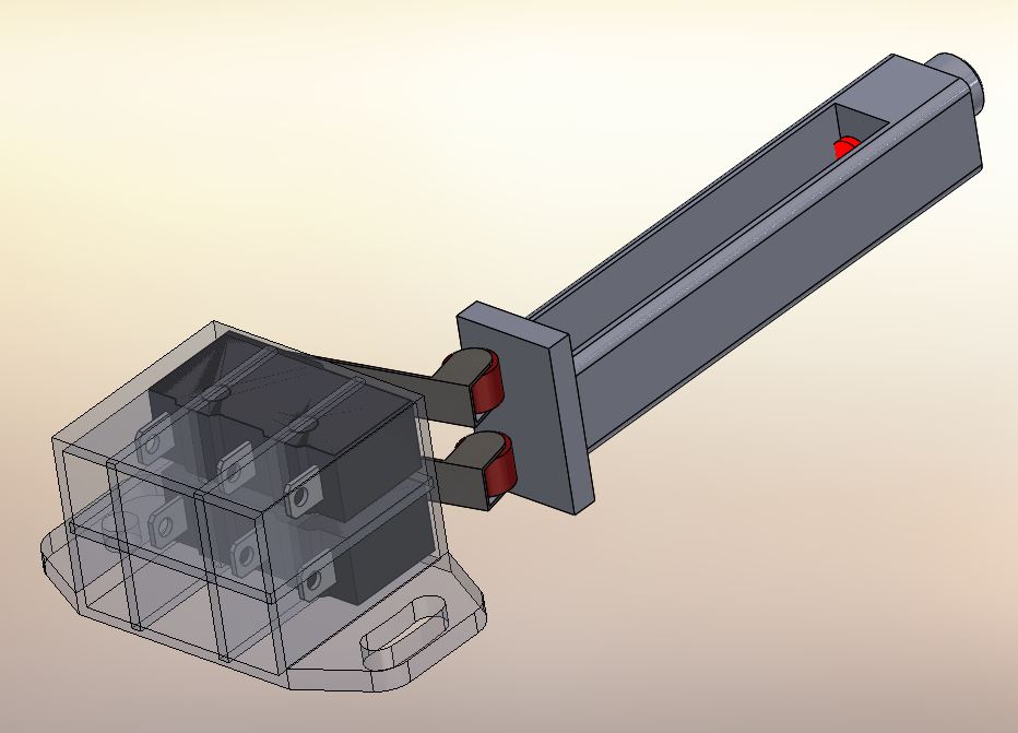
Warning : SPI1 has to be free ! Pins GPIO16, GPIO19, GPIO20 and GPIO21 (= 36, 35, 38 and 40 on the header) !

This is made easy with the included makefile, after cloning the repository using the SSH terminal ; then change directory to the clone repo.

3 options :

Typing just make will build the service : "marlin_osd.svc".

Typing make install will build the executable, copy it to /root/run/systemd/system, then create the etc file in /root/etc/systemd/system, "register" the service, and start it.

Typing make uninstall will completely undo what "make install" did, removing the files from the system directories.

Installing the service isn't even needed. just make and run ("./marlin_osd.svc"). There will be an error message about the SPI overay, it is normal.

Will also work with VNC :

sudo nano /root/.vnc/config.d/vncserver-x11

add BY HAND :

	CaptureTech=raspi
	IdleTimeout=0

(never worked for me copying/pasting from my notes :joy: )

(assuming you have a display defined in config.txt, X11, a window manager and a browser installed on your server !)

Currently learning how to add the service sources to the distro, and compile it : analyzing Octolapse's setup.py and directories structure !

update...

  • no more service in the background : sources are compiled at install time, and the executable is launched when OctoPrint starts

  • demo mode : it is the default mode, no need for hardware to get an idea of what this thing is doing ! Dispalys when OctoPrint starts, 50% transparency, 50% size.

The executable does not write to config.yaml (the plugin settings pages do).

Could someone be kind enough to test it ?

[GitHub - yet-another-average-joe/OctoPrint_MarlinOSD_Plugin](https://Marlin On Screen Display plugin)

The button is between GPIO4 and ground (or a female-female jumper).
GPIO pins in use : GPIO4, GPIO5, GPIO6, SPI1 (2nd device, CS being GPIO16)

A scrennshot showing the new main settings pages. Functionnal without hardware attached. Of course, the fake Marlin UI will display on the Pi monitor only (and in VNC with proper settings).

1 Like

ST7920 emulation is now supported : the printer motherboard is now able to display Marlin on a Raspberry Pi running OctoPi/Octoprint with the Marlin display driver set to the RepRap Discount Full Graphic Smart Controller in the printer firmware.

#define REPRAP_DISCOUNT_FULL_GRAPHIC_SMART_CONTROLLER

Most if not all old/current/future versions of Marlin have been supporting/support/will support this display unlike the SSD1306 OLED ; no more need to tinker under the hood (OTOH, it's just 5 lines...). But it is still recommended : 2560 bytes @600KHz vs 1048 bytes @1MHz with the SSD1306 (for a 1024 bytes image) ; the RepRapDiscount Full Graphic Smart Controller was born laggy and inefficient, and there's nothing that can be done !

OLED : 15ms* from the printer sending the first bit to the last bit comming out of the hat
RepRap thingy : 60 ms !!! maybe the decoding algorithm could optimized a bit, but the problem is the bloated data.

There's a 7ms to 40ms more display lag on the RasPi side depending on the image quality setting (oversampling) in the OctoPrint plugin. (medium : 22ms and high : 40ms settings are for sharp VNC video capture)

The emulation is set using the 4 jumpers on the hat PCB. See schematics and silkscreen.

New sources for the firmware : GitHub - yet-another-average-joe/MarlinOctoHat_v2

  • [EDIT] now 12ms after full optimisation.
1 Like