Agreed. Mine actually targets 5.2v.
Also pay attention to the efficiency of the buck- many do a poor job at that and will shed a lot of heat when you get above 2A.
Agreed. Mine actually targets 5.2v.
Also pay attention to the efficiency of the buck- many do a poor job at that and will shed a lot of heat when you get above 2A.
These are great tips and ones i wouldn't have known! Will bump up to 5.1-5.2v.
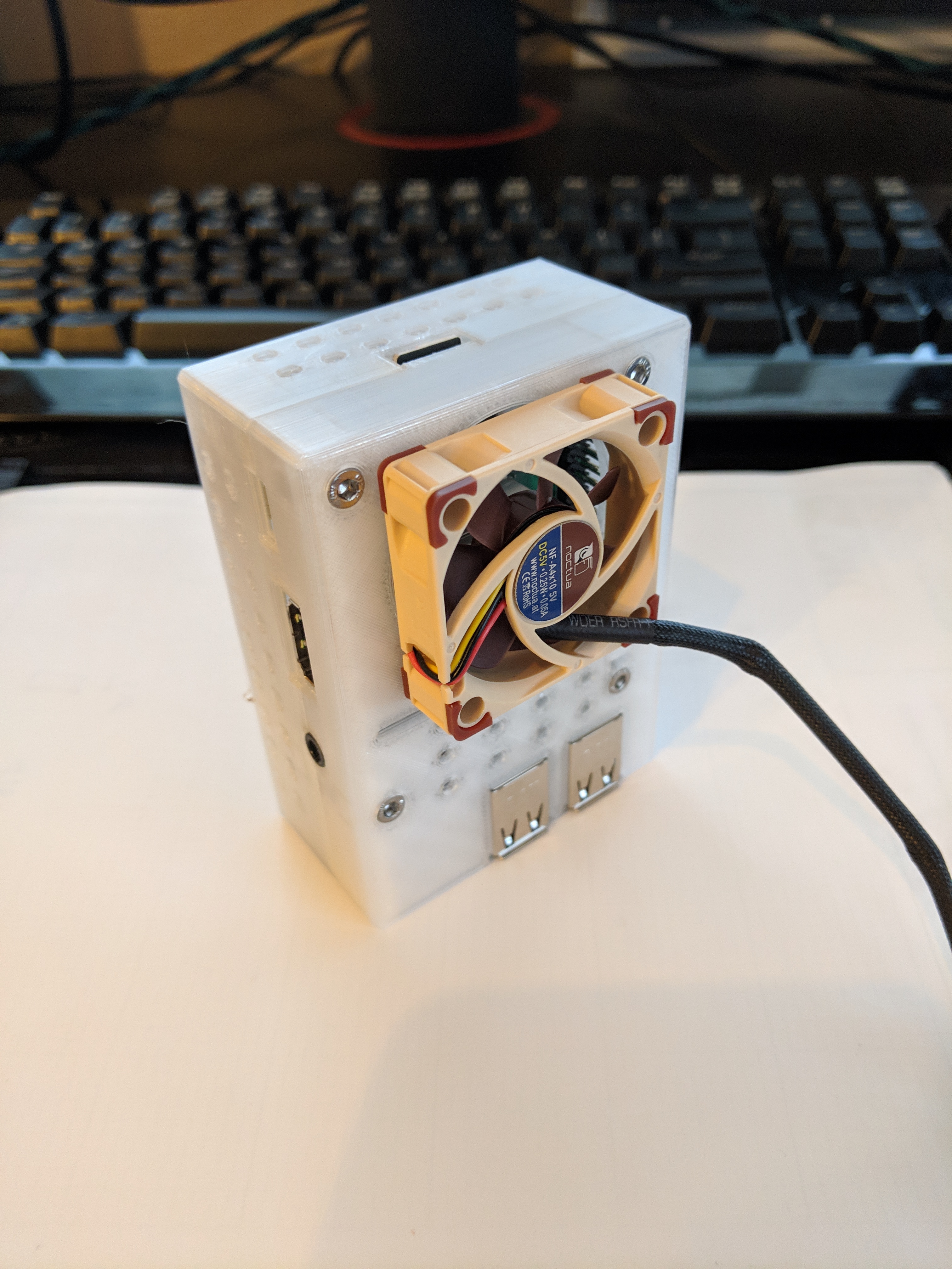
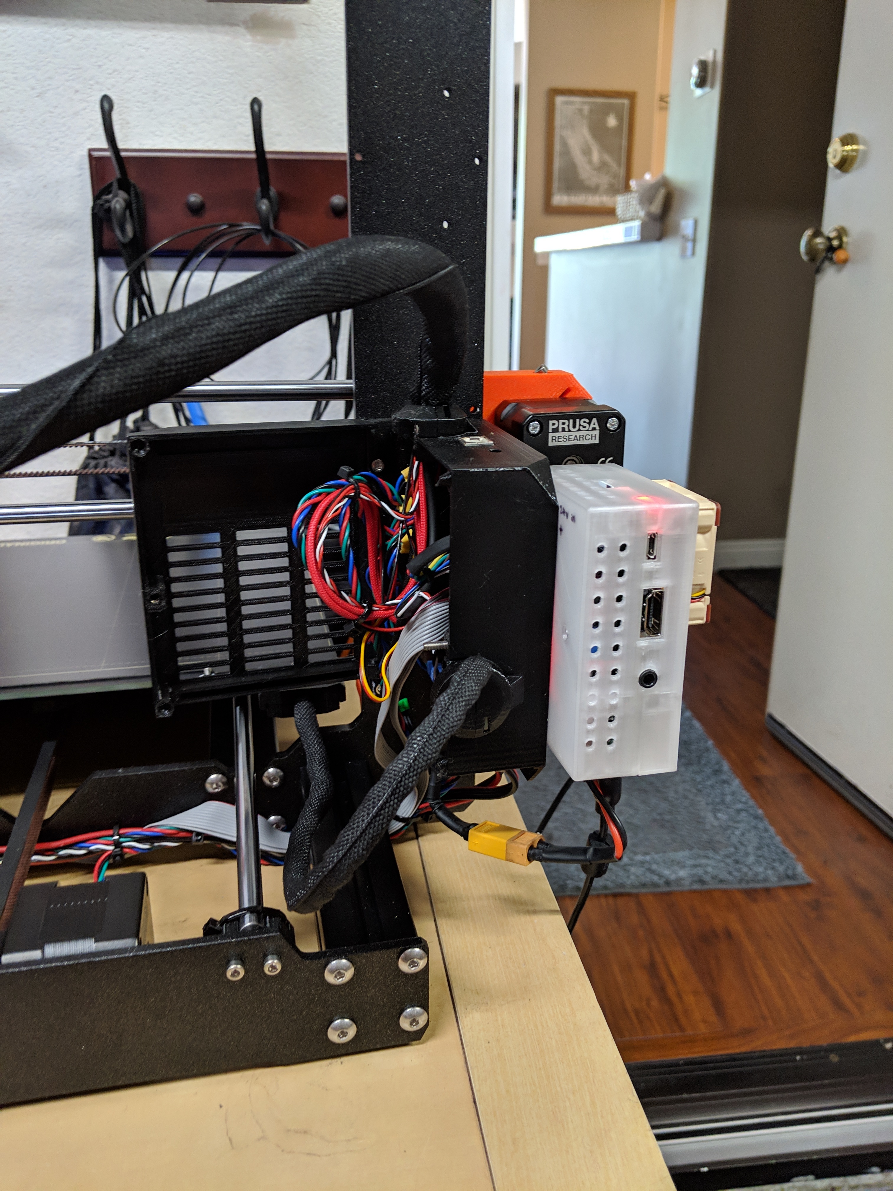
The buck converter is a cheap part off Amazon so i think its safe to assume its not that efficient. It does generate some head (~medium let's say) which is why I'm thinking I should have a 40mm fan to cool the RPi 3b+ and the buck converter if both are crammed into the same box.
If anyone has any tips/guidance/resources I can dive into to figure out how to wire the 40mm fan to the RPi 3B+ and have it programmed to turn on when a temperature sensors reads a certain amount, still looking for that info. I suppose the easy route is have it always on and powered by the 5-5.2v output contacts of the buck converter but I'm worried about dust long term which would be another thing to maintain & clean out.
I will share my case that I will model when that's ready for other to use as well.
If this were my project I think I'd go bigger on the gauge of the wires which power all that. Engineers will usually be under the constraints of budget so they'll choose the smallest wire that by spec will do the job. In that case, though, it usually results in a wire that's warm to the touch during operation which means it's dropping voltage in the form of that heat it's creating. It might not be much but I'd rather just use a bigger wire (damn the cost).
I ran some calcs (which I need to triple check) but based on ~3 foot length, 20 gauge copper wire, +5v, the power/ground wires i'm using should allow up to 167 amps (!). This seems very high and much more than the ~2.5 amps the RPI 3B+ should pull at most (plus additional current from 5v 40mm fan and camera but i'm assuming i'm well under 167 amp? For kicks, I calculate 30 gauge wire (3' length, copper wire) comes out to 16 amps. If my math his correct, in theory, i can go even thinner than 30 gauge and still be okay (not that I plan to switch).
Am I doing the math wrong?
I will of course feel the wire for heat as a gut check as well.
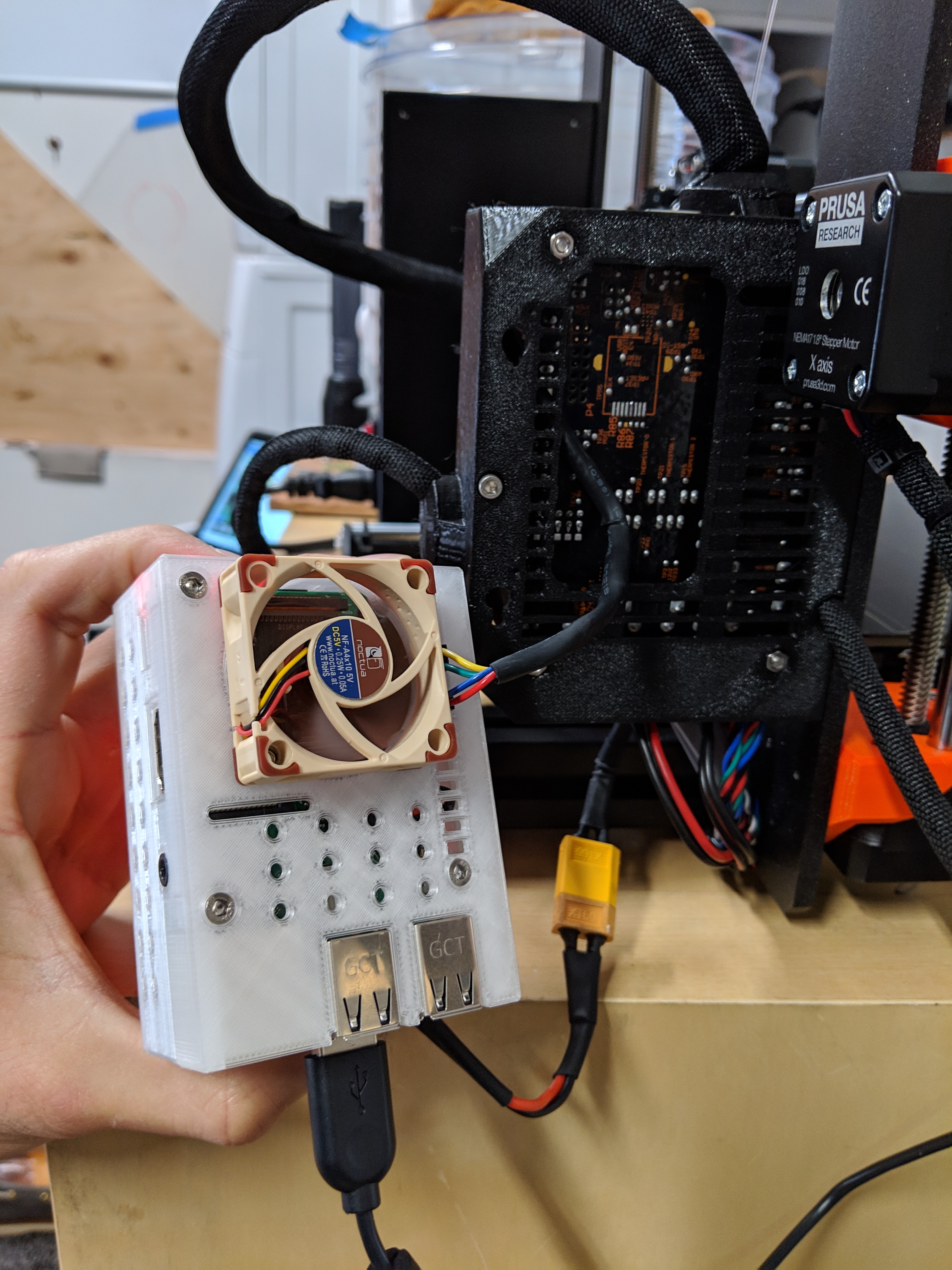
Last time I ran those numbers for 2-3ft of wire, an acceptable loss (2-3%) put me at 18ga. That's for the power side, which is 24v. The 5v side should only be a few inches from the buck to the board, which (in the pics) you were running over dupont jumpers.
Ah hah... rookie mistake on my part! i was mixing up the power side (+24v, ~2-3 foot long side) and the +5v side which is currently hooked up with the 4-6" dupont jumpers as you're pointing out.
So if you calculate 18 gauge will do the job, my usual wisdom quirky behavior is to drop that down to 16 gauge.
My rationale is that this will lower the loss slightly, lower the temperature slightly... and over time this will mean that the wires won't deteriorate (usually at the ends). One of the ingredients for making corrosion is heat, btw.
Took my time with the calcs and made some conservative assumptions...
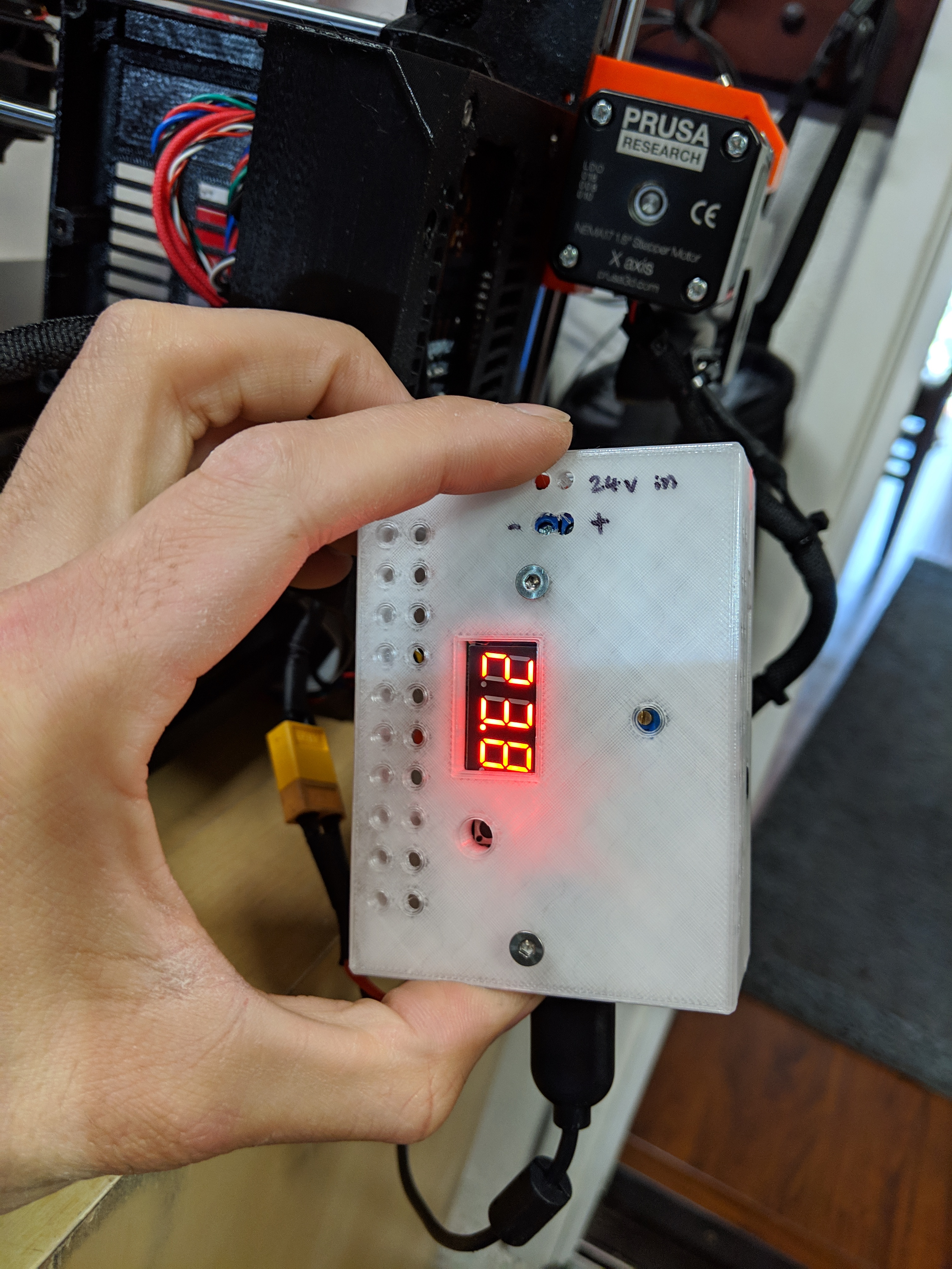
On the 24v side I should need 22-24 gauge wire for it to drop 3% v. I'm running 20 gauge so should be okay on this side.
On the 5v side, at 24 gauge (assumed gauge of current temp jumper wire), I should run less than 7" length (currently 8") at full load. It will likely be 20 gauge wire on this side at ~2-4 inches length when I solder it so should be good here when its made permanent.
The Pi 3's are Amperage piggies. They really want 3amps @ 5 volts. If you push them, they get unhappy. I'm thinking of taking an ATX power supply, as many YT videos show, splitting off the 12 & 5 volts and putting in testing probe (aka your volt/amp/ohm meter) ports installed. It looks pretty simple, but that RadioShack is gone. Then I've got 300A of 5volts. or so... I have to do my Volt/Ohm/Amp calculations. Those guys that just played in the 1700's
I just received a new Pi 3 B+ to replace a much older Pi B+ and have it hooked up to the 24V supply on my Ender 5 via a cheap DC-DC converter. Works very well except I have to remember to shut-down the Pi before powering off the printer.
I'm just setting up a Pi Zero W as a camera and it will also connected to the DC-DC converter.
Maybe a UPS and automatice shutdown on power loss?
I've been watching youtubes in to learn how to control a 5v fan with th RPi 3 and have it power on/off as a function of temp. I suspect there's got to be a way to hookup a battery pack or possibly even a capacitor to keep the RPi 3 on for a brief period of time if there is power loss.
1500W sounds like a pretty big power supply.
You'd want to review the specs for it, though. It won't pass all of the "big number" in watts to a single rail (like 5V). In fact, in some cases if you don't load the 12V rail at all and try to load the 5V rail heavily it won't work right.
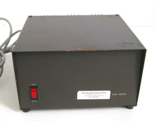
Just guessing here, but you might see 15A at most on the 5V rail coming out of even the biggest ATX/SFX power supplies. (Years ago, I owned a Radio Shack 20A 5V power supply for my datacenter and it was bigger than an average SFX power supply and certainly heavier.)
Look how beefy this 20A 5V power supply was and this is dedicated to just a single rail:
I'm currently working on a plugin for APC-branded UPSs, for what it's worth.
Here's another thought:
Mean Well 5VDC 5A Power Supply
This provides 5VDC 5A, from an AC input. Connect it directly to the main supply and you'll have enough for your Pi 3B+, camera, etc. If you put it before the switch, the Pi is independent. Put it after, it goes on and off with the printer, although you have to be careful about issuing the shutdown command to the Pi, first.
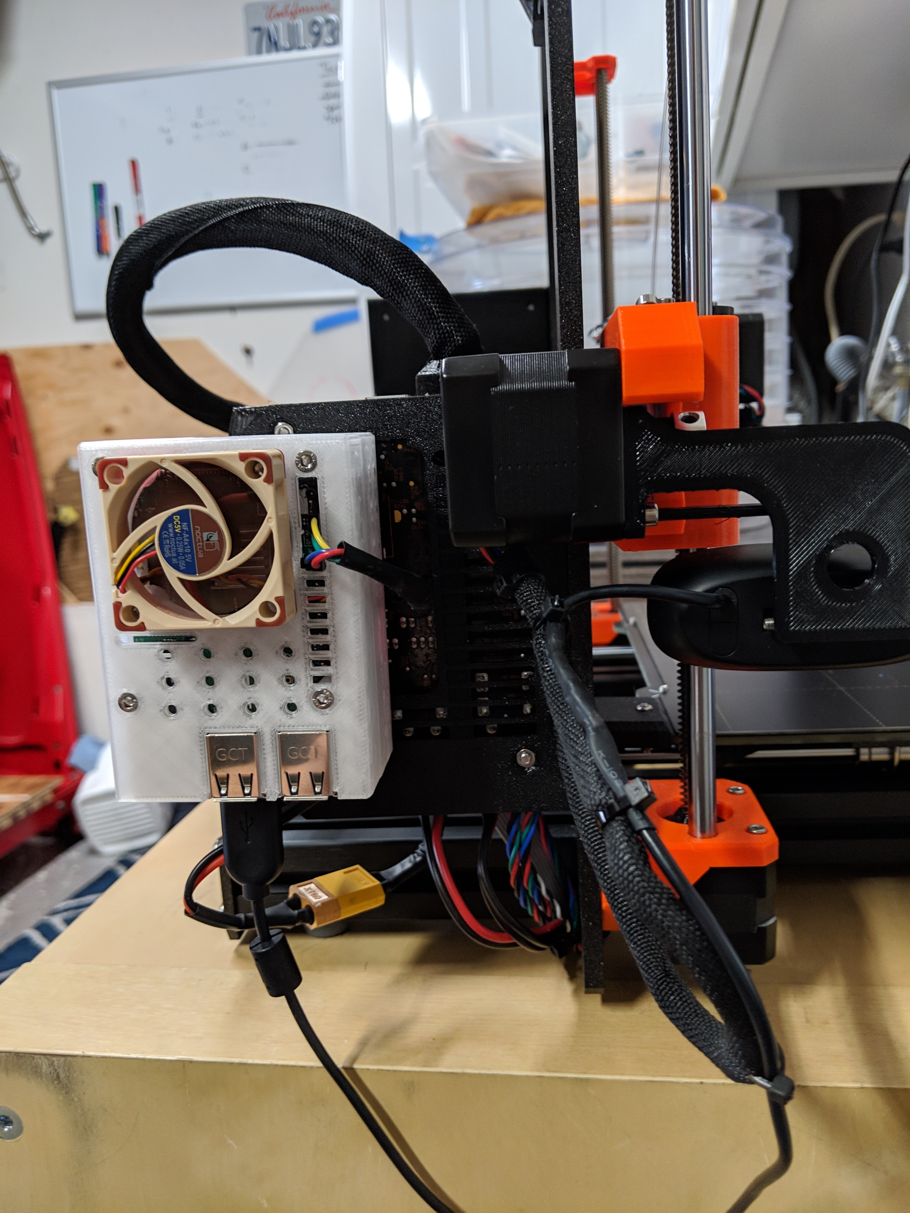
I got thru my install and it seems to be working great!
I used a 40mm 5v Noctua fan, wired to the 5v output of the lm2596 step down voltage regulator.
the case took about 12-16 hours to draft :-/ and its still not perfect.
When i find myself with too much time, i will probably make a few tweaks to my case (i drilled some holes i didn't need) as well as the factory mobo case to my mk3s to get everything perfect. I also want the fan to turn on when the CPU reaches a certain temp but that's another phase of the project...
Nice. I recently modified my pi case to incorporate a noctua 5v fan that i connected directly to the pi's 5v and ground pins. Figured always on is good for my situation since those fans are so quiet. @tedder42's octopi support plugin kept warning of CPU capping due to overheating, and I figured I might as well fix it...my case was completely closed without any vents prior.
Did you drill the screw holes or model them? I've got a clever technique of modeling the bolt holes in Fusion 360 if you're interested.
I just used the a hole tool... nothing crazy. There are a lot of sloppy features in my model. i don't plan to sell it and no one will know unless i tell them so i will probably not correct them.
I ended up just deleting the separating parts of the USB/Ethernet jacks in my case and left everything else solid. Seems to draw the air nicely across the board. If I remember correctly, temps were showing ~39C after putting it all back together.
You saw my snazzy cover? I put holes and slots in the ‘scad.
@Roger_S That is a snazzy idea. would you share your case model and an outline of your trails? I'm running a Pi 2b on my Mono Mini, going to a multi-port USB PS. I have the voltage monitor plug-in installed & have never seen a flag. My CPU ala 'top" during a print job runs 15-40%. A little memory and no swap. My 2B is not taxed. I am using eth0 not using wlan0. I have 3 primary workstations I connect with to submit jobs. A HP mini110 - ATOM i686 w/ Lubuntu, an Original Samsung Chromebook, and my Pi3b+ that I use as a workstation. I'm essentially in a low power CPU usage environment. I watch power monitoring. I'm running enough Pi's now that I'm pondering putting NAGIOS on a PiZW, just to watch my devices ala SNMP. Those are my findings, thoughts, ideas. IMHO
JLH