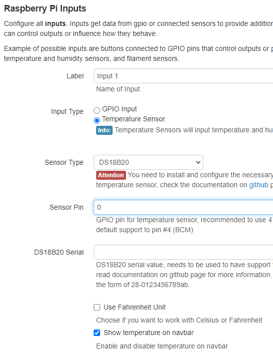
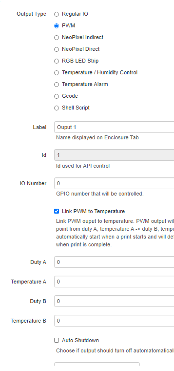
I built an enclosure for an ender 3 and I would like to add active heating to it. I have added a DS18b20 thermistor on gpio 4 as an input and I would like to add an output to control a heater, actually an SSR that controls the heater. I set this up as a pwm output on gpio 13, linked it to the thermistor input to get the value to be used. My question is when this is checked "Link PWM to Temperature" there are 4 values that need to be entered : Duty A, Temp A, Duty B, Temp B. I'm not sure what temps should be entered here, if my ideal temp 60c should Duty A and Temp A be set to 100, 40c and Duty B and Temp B be set to 0, 80c hitting the average at duty 50, 60c? Is this the correct setup to control an ssr controlling a heater?
If no one can offer advice how about documentation? I looked through the Enclosure wiki and saw nothing pertaining to what I'm looking for.
I think the Enclosure Plugin is going to be the only thing that is going to come close. It has support for your sensor.
And also linking to a pwm output based on temperature.
You would then command that through your slicer to add the appropriate Gcode for the other heater which is then grabbed by the Enclosure plugin.
Thanks for the reply. I guess I wasn't clear in my question...I have the above enclosure plugin installed and that's what all the settings from my original post are from. I have 3 questions, will using a pwm gpio work to control a SSR controlling a heater work? If so how would I set up Duty and Temp settings if the target enclosure temp is, say 60c? If pwm is not the "right" way to do this then changing the output to "Temperature" and temp control type to "Heater" what does "Value Deadband " refer to? For instance if the target temp is 60c and I put a value of 10 in "Value Deadband" is that acting as hysteresis, the temp has to drop by 10 before the heater turns on again?
By SSR do you mean Solid State Relay? What type heater do you have hooked up to a Solid State Relay that would need a PWM signal? I would think you would want just a simple digital signal to either turn the relay on or off and therefore turn the heater on or off. Of course, that would depend on what kind of heater you have connected.
The deadband is the difference between the heater turning on and turning off. Yes, that is acting as hysteresis.
Yes, Solid State Relay. The heater is a 150x150 silicone heater adhered to a150x150 aluminum heat sink. I guess a simple on off relay would work. Thank you you for your help.
Can you tell me how the gpio pins should be set up? If I'm using gpio pin 26 connected to the relay would I connect the other pin of the relay to ground or vcc?
Well, first of all, you have to make sure that you have a relay that is compatible with the Pi. Second of all, you have to make sure your relay will support your heater on the switched side. A mechanical relay is going to be a lot better since it will not have any leaked voltage like a solid state relay will. What is the voltage of the heater? Are you trying to switch mains power with a solid state relay connected to your Pi? That's a really good way to blow up your pi and at worse, kill you in the process.
The heater is 120v, so it will run on mains power. How will running an SSR blow up the pi? I've wired up a heater bed on another printer with ssr/mains power, pwm switched by a BTT GTR mother board with no issues. I understand the dangers of handling 120v/30amp power. If it's better to run a mechanical relay then that's what I'll do, but I'm still curious how using an ssr will blow up a pi?
I can't quite agree. SSRs are optical isolated up to a few hundred volts.
On my Trex-3 a SSR is controlling the 240V heated bed.
And that is inside your printer. Not connected to the GPIO pins on a Raspberry Pi. LOL...i give up. Do whatever the hell you want. When someone gets hurt, don't say you weren't warned.
I would never use something that is not protected and secured to switch mains voltage. Period. Low voltage, like 3.3-12 or even 24v, sure. But all my mains powered switching is done by purpose build devices, like smart power strips or Sonoff devices. Yes, they can be "hacked" to control them but that does not remove the in-designed safety features, like having covered connections for all mains voltage and physically isolating the low-voltage circuit from the high voltage circuit. If that mains power becomes disconnected from the relay and touches the Pi, it's dead.
No need to be snarky, please explain why this will blow up the pi? I'm just trying to learn. I set up the ssr to mains to power my heated bed using the heated bed output of the mobo to trigger the ssr. It did not blow anything up and I survived. I realize that it was not a pi that is why i'm asking here to get good advice so i don't blow anything up. To repeat my self, for the gpio pins on the pi do I want to use a vcc pin and a gpio to go low or ground and gpio to go high to trigger the ssr or mechanical relay?
I'm not being snarky, i'm trying to keep you from killing yourself.
If you don't know how an SSR works, you should not be using one to switch mains voltage.
so what you're saying is that using hardware outside of it's intended use can be dangerous, not that the actual method of wiring is wrong?
I am aware of how an ssr works...I'm not aware of how a pi should trigger an ssr or any relay...that is, going high, providing vcc or going low providing ground...which is the preferred method in this use case? The printer mobo was easy, it was set up to power a heater bed so the output goes straight to the ssr, the pi is not so straight forward...at least not to me, I'm just not that familiar with pi.
That's the purpose of a SSR: to be protected.
And it's usually better isolated than a mechanical relay.
It seems we are getting lost on the virtues of ssr vs relays vs powertails and how safe it is. How would one wire up a pi to control a ssr, relay, powertail? vcc+gpio pin or ground+gpio pin? Or another way completely?
I'm moving forward with running 5v power from pin2 and gpio17 pin 11 to the ssr. When the heater is turned on from the pi the ssr is switched so it looks like it works. I will be printing a cover for the ssr so there are no exposed terminals.
1 Like