I can load a version of Marlin on my Ender 3 V2 that supports filament runout detection with the sensor connected to the printer motherboard. But, I read a post that says that won't work if using Octoprint, since Octoprint will have no way to know the runout event occurred and will just keep sending GCode.
On the other hand, another post said that there will be a long delay between when sensor indicates runout and the GCode quits streaming from Octoprint, if the connection is made to a RPI gpio. Probably too long a delay so that the end of the filament moves too far past the sensor and into the Bowden tube making it hard to remove.
So, what's the preferred way to connect? I could connect to both, I guess.
Also, will Octoprint respond to an RPI connected sensor if the printer is printing from its SD card?
Connect it to the printer, and in your version of marlin enable HOST_ACTION_COMMANDS and HOST_PROMPT support in the firmware. Then, it will be able to tell OctoPrint, OctoPrint will pause the print.
2 Likes
Ok! I'll give it a try today.
Thanks!
So, in this code fragment:
#define HOST_ACTION_COMMANDS
#if ENABLED(HOST_ACTION_COMMANDS)
  //#define HOST_PROMPT_SUPPORT
  //#define HOST_START_MENU_ITEM  // Add a menu item that tells the host to start
#endif
Uncomment #define HOST_PROMPT_SUPPORT but not HOST_START_MENU_ITEM?
Definitely host prompt support, start menu is optional. If there is a print loaded via OctoPrint, the printer can tell it to start printing (equivalent of the big blue print button). I personally use that, since I load up the print, then sometimes go to swap the filament - I can then just press print on the display of the printer.
1 Like
When I issue a M412, I get
Send: M412
Recv: echo:Filament runout ON
Recv: ok
Can I conclude the newly configured Marlin firmware that enabled runout sensor got loaded?
The runout sensor is connected to Ender 3 V2 connector. When the the switch is open, the print continues normally. When I close the switch, the printer stops immediately, no further head movement. Octoprint reports a serial disconnect.
There's a picture of Ender 3 V2 motherboard with the3 pint runout sensor connector shown. It shows gnd as the middle pin, +3.3 on one side, and the sense pin on the other. 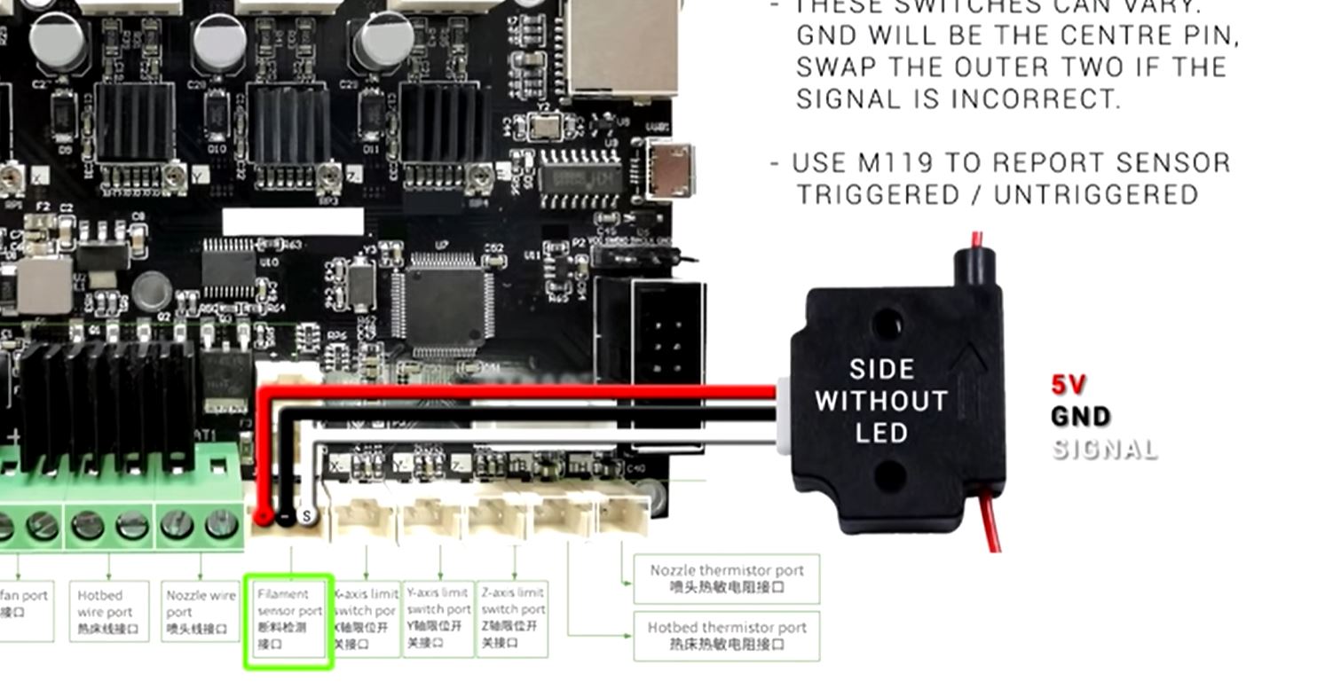
I used a DVM and measured 3.3v between the red( +) and - (black) pins (as expected).
I'm just using a limit switch with no LED, so I just used the pins that the picture shows connected to the black (-) and white (S) wires.
I found one post where an individual said that picture was wrong, but I saw no confirmation nor what the correct pinout was. If closing the switch actually connected 3.3V to gnd, I'd probably see these symptoms. But, maybe something is going wrong in the Marlin code when the S pin goes low.
Any suggestions?
I confirmed the new firmware got loaded by using M115:
Send: M115
Recv: FIRMWARE_NAME:Marlin bugfix-2.0.x (Jan 26 2021 10:29:53) SOURCE_CODE_URL:https://github.com/MarlinFirmware/Marlin PROTOCOL_VERSION:1.0 MACHINE_TYPE:Ender-3 V2 EXTRUDER_COUNT:1 UUID:cede2a2f-41a2-4748-9b12-c55c62f367ff
Recv: Cap:SERIAL_XON_XOFF:0
Recv: Cap:BINARY_FILE_TRANSFER:0
Recv: Cap:EEPROM:1
Recv: Cap:VOLUMETRIC:1
Recv: Cap:AUTOREPORT_TEMP:1
Recv: Cap:PROGRESS:0
Recv: Cap:PRINT_JOB:1
Recv: Cap:AUTOLEVEL:1
Recv: Cap:RUNOUT:1
Recv: Cap:Z_PROBE:1
Recv: Cap:LEVELING_DATA:1
Recv: Cap:BUILD_PERCENT:0
Recv: Cap:SOFTWARE_POWER:0
Recv: Cap:TOGGLE_LIGHTS:0
Recv: Cap:CASE_LIGHT_BRIGHTNESS:0
Recv: Cap:EMERGENCY_PARSER:0
Recv: Cap:PROMPT_SUPPORT:0
Recv: Cap:SDCARD:1
Recv: Cap:REPEAT:0
Recv: Cap:AUTOREPORT_SD_STATUS:0
Recv: Cap:LONG_FILENAME:0
Recv: Cap:THERMAL_PROTECTION:1
Recv: Cap:MOTION_MODES:0
Recv: Cap:ARCS:1
Recv: Cap:BABYSTEPPING:1
Recv: Cap:CHAMBER_TEMPERATURE:0
Recv: ok
Send: M155
I can confirm the pin out in that picture is wrong. The S and + pins are reversed.
Instead of just closing the switch, I tried using a 4.7K resistor between the pins labelled S and -. The S pin remained at 3.3V. This indicates something much lower than the 4.7k pulldown was holding up. Probably connected directl to 3.3V.
So, I tried using the pin labelled as + (red wire) as the sense pin. Now, when I used the 4.7k resistor across the + and - pins, the + pin went to zero volts. This is as expected, if the + pin were actually the GPIO input (S) pin.
So, I tried closing the switch with the wiring corrected during a print. The printing stops, the printer starts beeping, the head raises and moves to the corner. The printer starts beeping.10 times slow, then 5 times fast.
I can use the print button on the LCD to start the print again. So I guess its working!
Thank!