I am using the PS-ON pin to control my main PSU with a relay, and would like to use the functionality of the PSU Control plugin to show me if the PSU is on, and activate it (or deactivate it) as needed.
My Marlin configuration also has the PS_ON pin automatically controlled by the firmware, so in 99% of use cases, I don't need to use the plugin to activate the PSU, because the Marlin firmware does it for me.
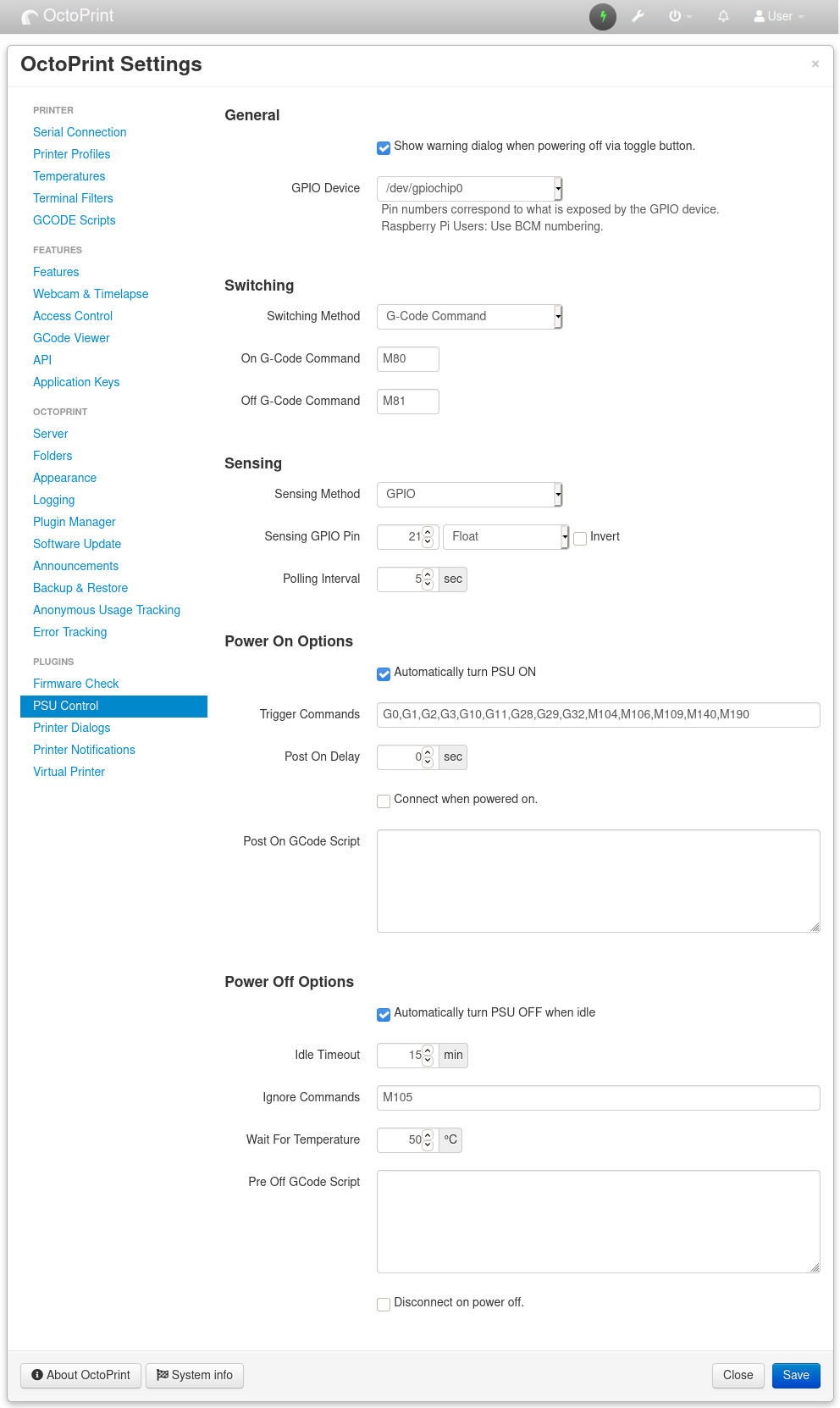
The PSU Control plugin will control the PS_ON pin fine with M80 and M81 commands, but since I don't need those most of the time, I would like the plugin to poll M80 S every minute or so to update the status of the PSU in the UI. This M80 S G-Code will return PS:0 or PS:1 to indicate the status.
There are several options for 'Sensing' in the plugin, but G-Code isn't one of them. Am I missing something, or do I need to make a feature request for this.
There was an early stages PR for this before sub plugin support. It can definitely be made into a sub plugin now but it's not something I'm interested in writing as I don't use it.
The trouble with using M80 S is that it requires a printer serial connection so in cases where it's not connected you have to make assumptions which is contradictive to the whole purposing of sense mechanic.
Another issue is getting the status during a print or during long running commands.
In my opinion it's not worth using M80 S when GPIO is available.
There was an early stages PR for this before sub plugin support. It can definitely be made into a sub plugin now but it's not something I'm interested in writing as I don't use it.
I'll have to take a look at how complex it is to write a sub-plugin... I'm not a software developer, but I can copy and paste code and make tweaks!
The trouble with using M80 S is that it requires a printer serial connection so in cases where it's not connected you have to make assumptions which is contradictive to the whole purposing of sense mechanic.
I'm not sure I understand the logic regarding serial connection... Why would there not be a serial connection? If you're using M80 and M81 to control the PSU, there must be a serial link because otherwise that wouldn't do anything and you wouldn't be able to turn the PSU on at all. Effectively, if you're using M80 and M81 for control, you must have your board powered separately from the main PSU and an active serial link.
Another issue is getting the status during a print or during long running commands.
I do take the point about during a print or during long commands. The worst case here though is that there would be a delay in getting the response isn't it?
In my opinion it's not worth using M80 S when GPIO is available.
Are you saying that it's not worth using M80 and M81 at all, or that there is some way I could determine PSU state using a GPIO pin, even though I'm not using GPIO for control itself?
You can send M80 and disconnect the printer or restart OctoPrint. If using M80 S you would have to wait for the connection again in order to know the power status even though it clearly should be on.
Delay and additional non-print related commands being sent over the serial link.
Quite the opposite. I use M80/M81 but sense from the Pi via GPIO against the PS_GOOD (you can also check against whatever the primary DC voltage is [12V/24 rail]). By doing this I can actually verify power is on instead of assuming.
This is great, thanks, but I'm now interested in the GPIO approach.
Understood, thanks.
Good point.
Would you mind elaborating on this? The board I'm using (Creality v2.2.1) doesn't have a PS_GOOD pin as far as I know, but I will check. If I wanted to use the 24v rail, would I need to run that through a buck converter before connecting to the GPIO pin to get the voltage down? It's then two wires to the RPi GPIO pin header, correct? Gnd and the signal that shows that the PSU is on?
There are a couple of ways to read a higher value voltage with a low voltage input. In my setup I use a simple voltage divider. It has some risk of damaging the Pi if there was a large voltage spike or the resistors fail(short) but I'm OK with that. A better way would be to use an optoisolator.
Not sure where you would need to tap into on the Ender but I'm sure there is something at the PSU side.
All makes sense, thank you. I was trying to avoid using GPIO, but once I move my RPi to a better location with a touch screen etc, I'll look in to this.