Make your own Sonoff smart plug

Hi :slight_smile:

There are a lot of cheap more or less "smart" wifi plugs out there and most of them are esp8266/esp8285 based.

I picked the cheapest I could find on Amazon prime and for this showcase I'll flash the Tasmota firmware on it.

Alternative firmware for ESP8266 based devices like iTead Sonoff with web UI, rules and timers, OTA updates, custom device templates and sensor support. Allows control over MQTT, HTTP, Serial and KNX for integrations with smart home systems. Written for Arduino IDE and PlatformIO.

.

:warning: WARNING BEFORE PROCEEDING :warning:

DO NOT CONNECT DEVICES TO MAINS POWER WHILE THE COVER IS OPEN AND CIRCUIT BOARD IS EXPOSED!!!

NEVER TRY TO FLASH WHILE YOUR DEVICE IS CONNECTED TO MAINS POWER!!!

YOU CAN BE ELECTROCUTED IF YOU DON'T KNOW WHAT YOU ARE DOING!

.

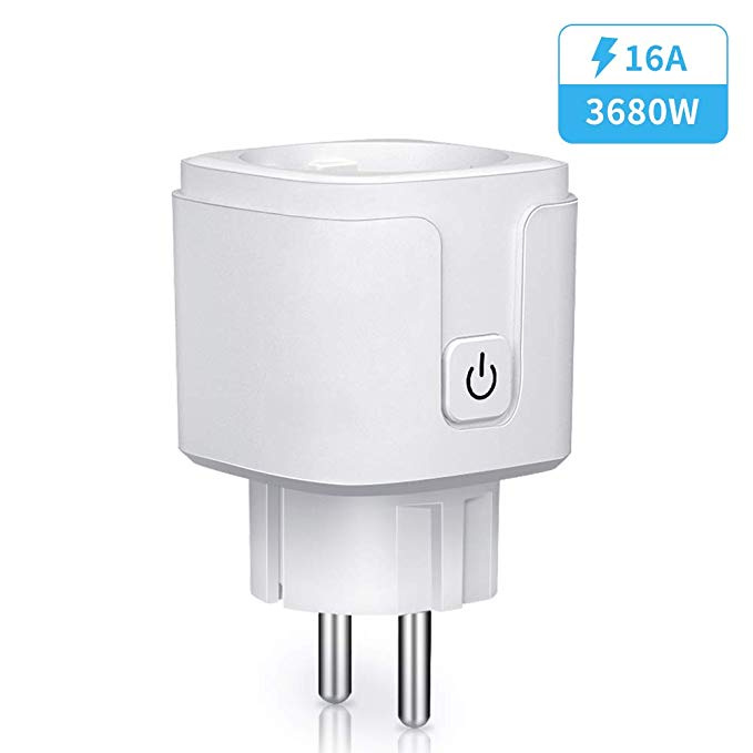
Let's start with the plugs on Amazon.


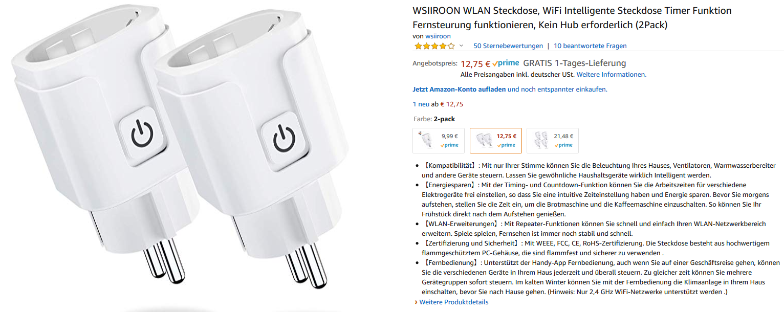
The description says that the plugs got wifi, timer functions, remote control and that you don't need a hub.
Further down it also says IFTTT compatible.

So I figured they are probably esp8266 based and ordered 2 of them :slight_smile:

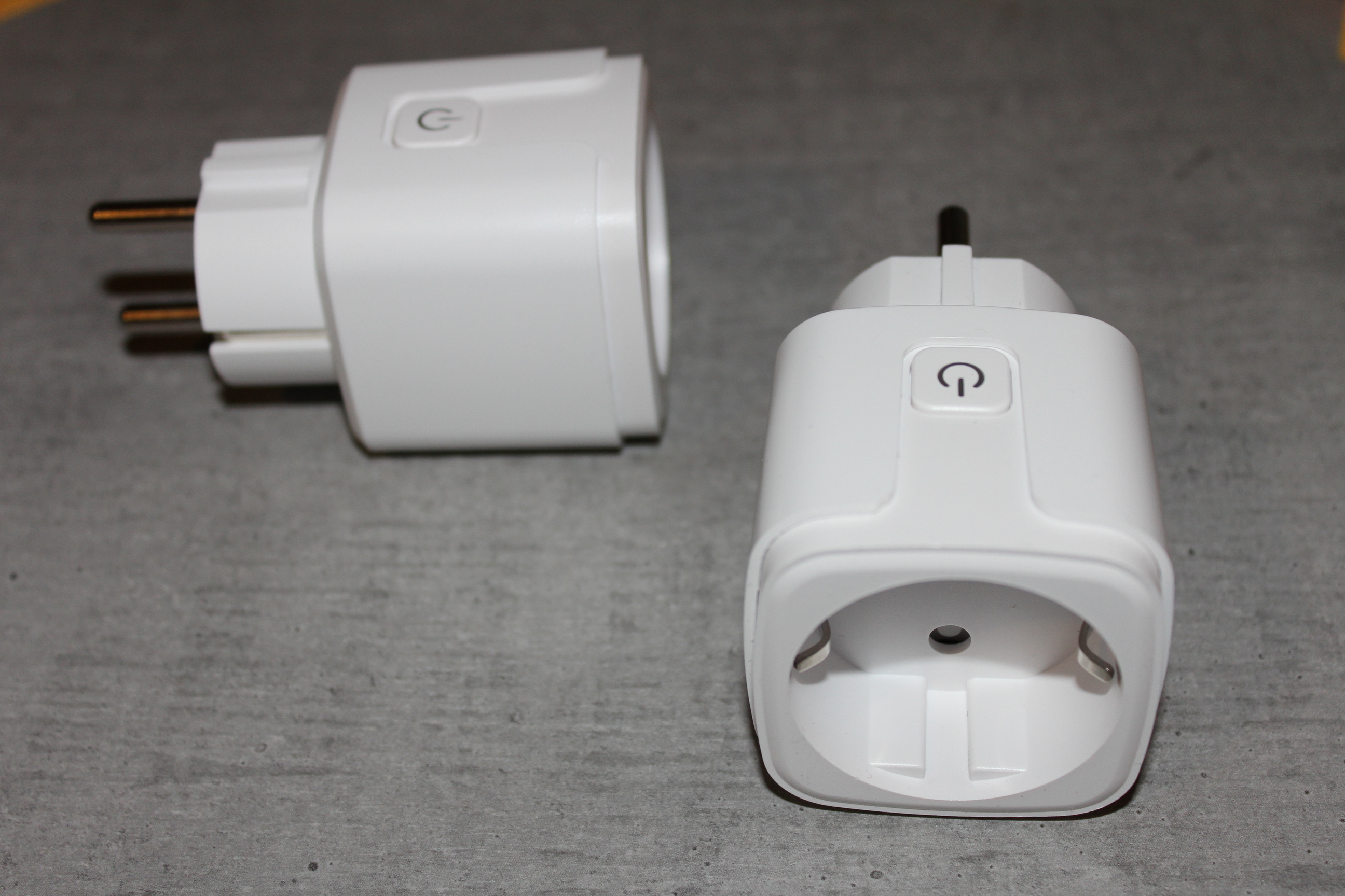
That's how they look like

Next thing to do is to open them and that is a bit of a pain in the butt. The case of the plugs is glued and not screwed :unamused:
So I opened them with the help of a screwdriver and a spudger


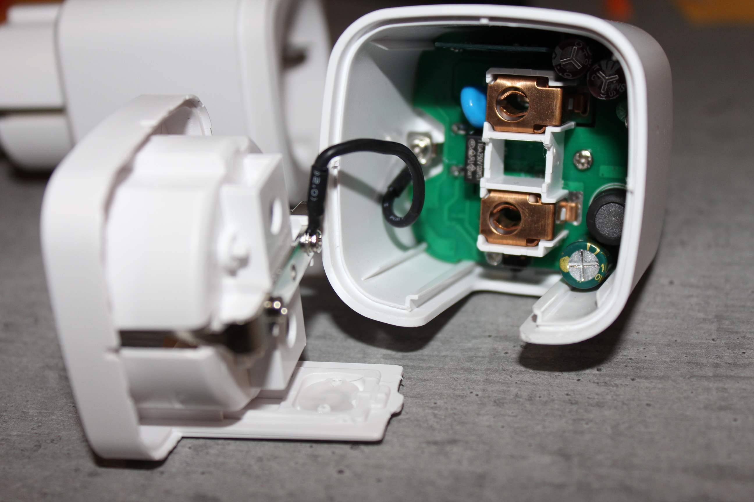
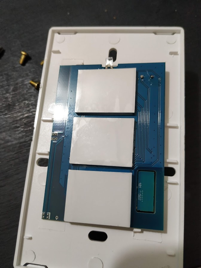
Now I remove the pcb

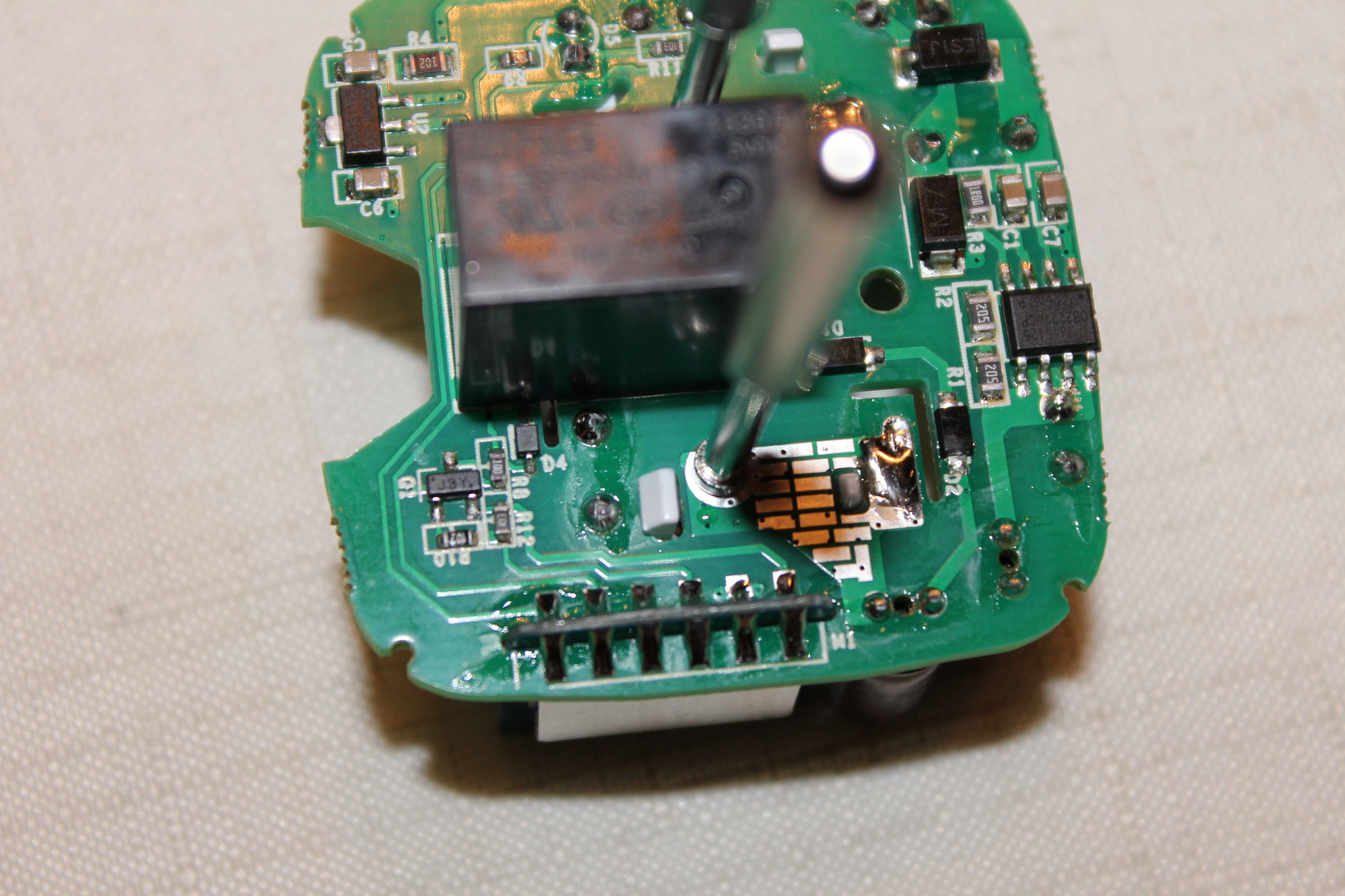
Here you can see the wifi module which unfortunately has no module name printed on

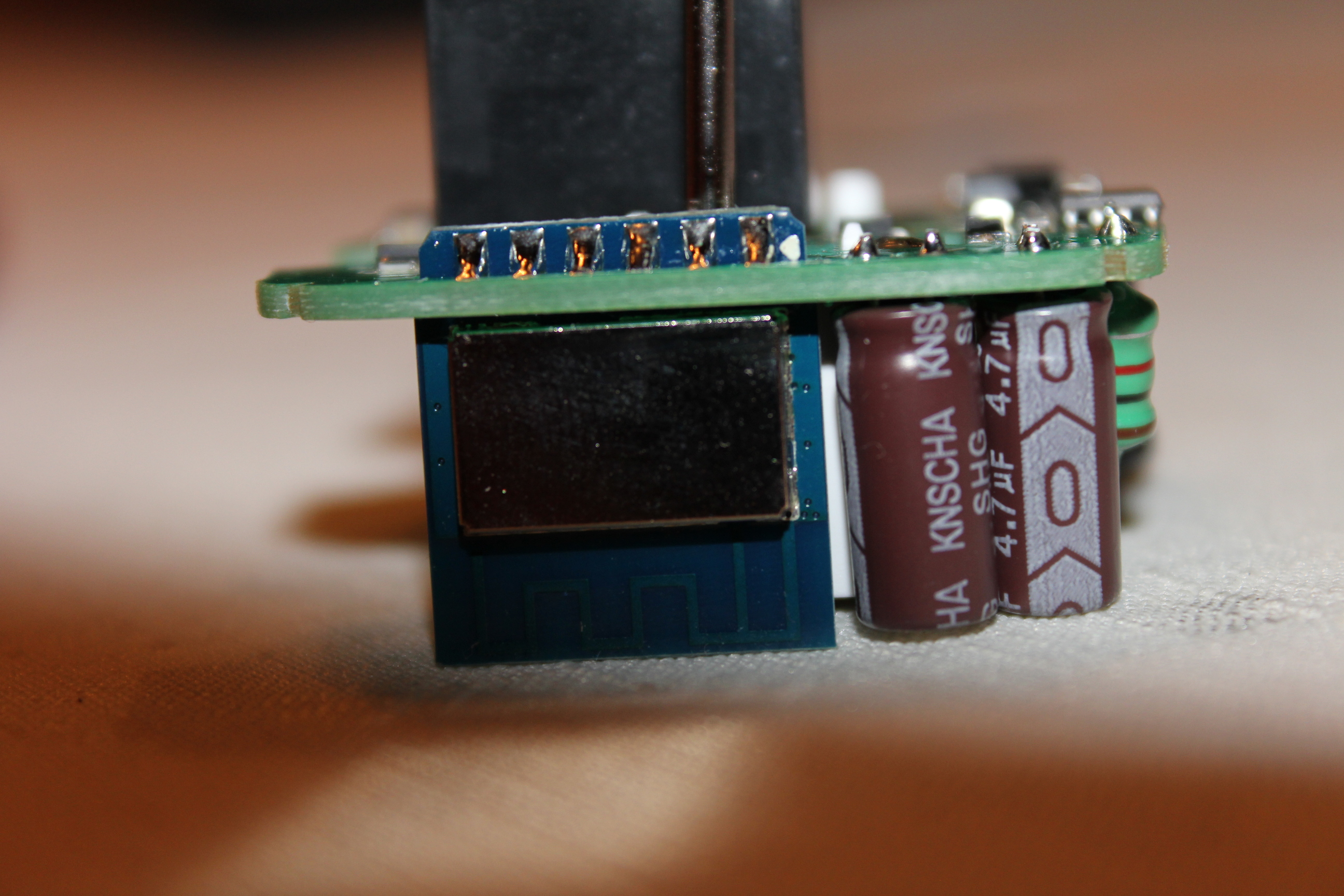
so I remove the shielding

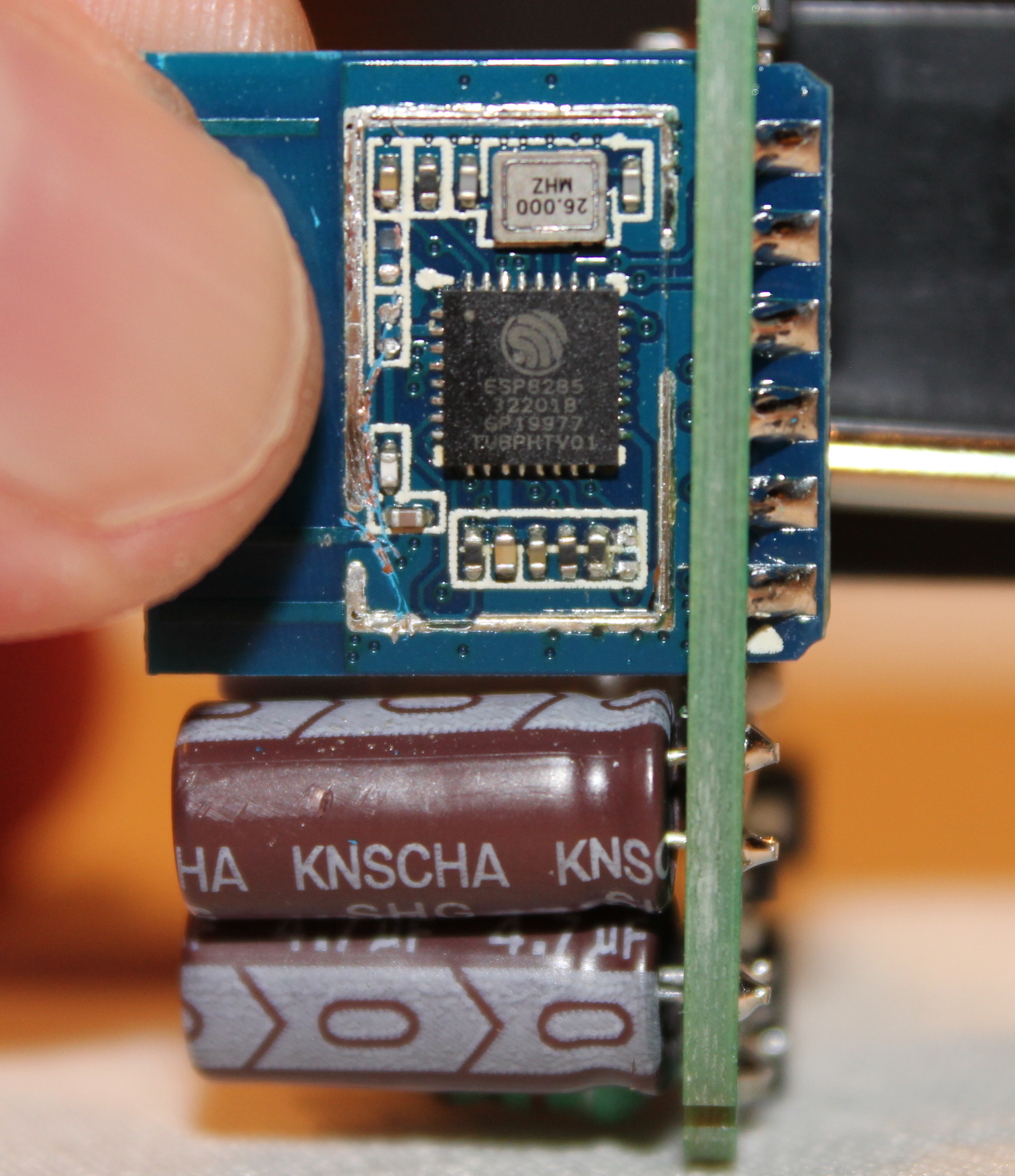
and as you can see it turns out to be a ESP8285 module. You don't have to remove the shielding - I just did it so I know what I'm working with.

Now I'm preparing everything for the flashing part.
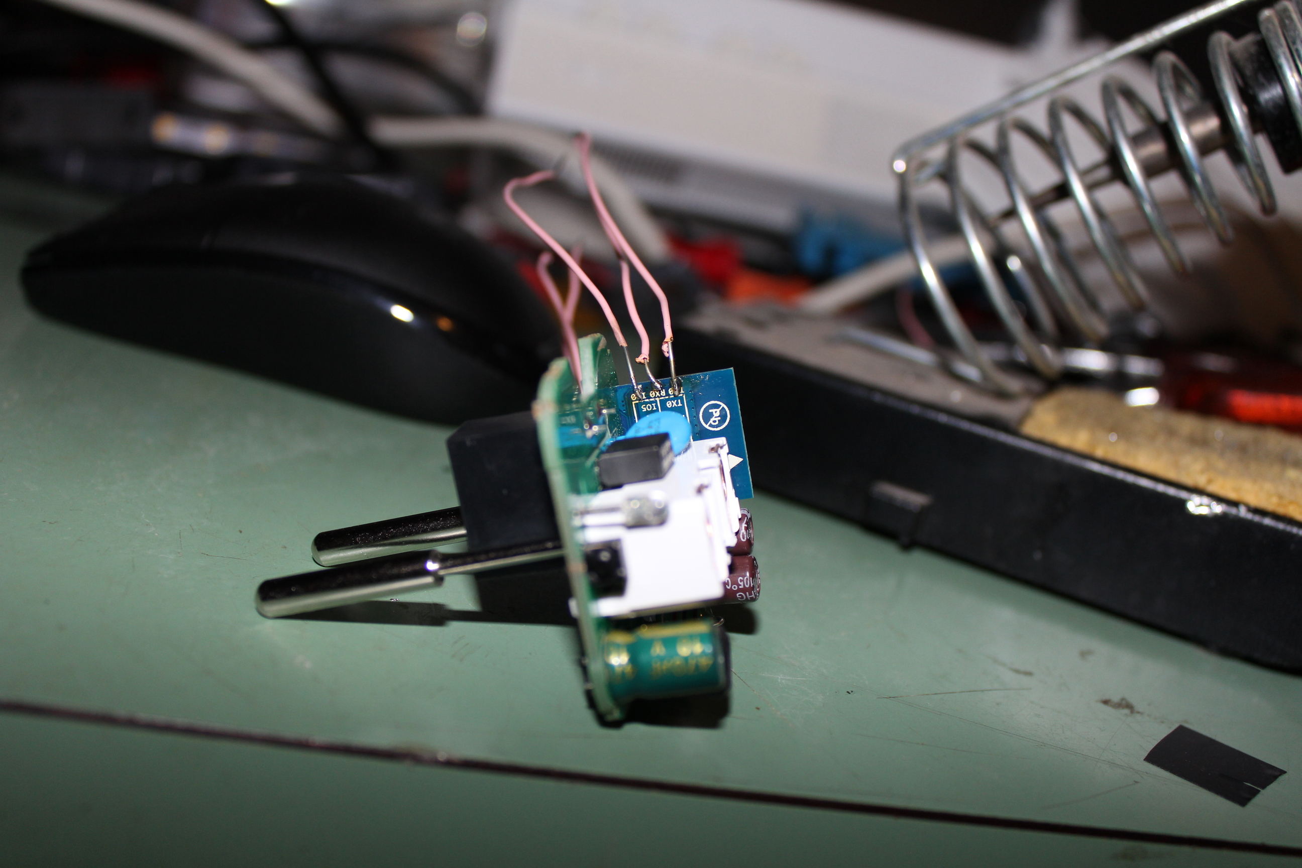
First I have to know the pinout of the module. Fortunately the pinout is printed on the back of the module

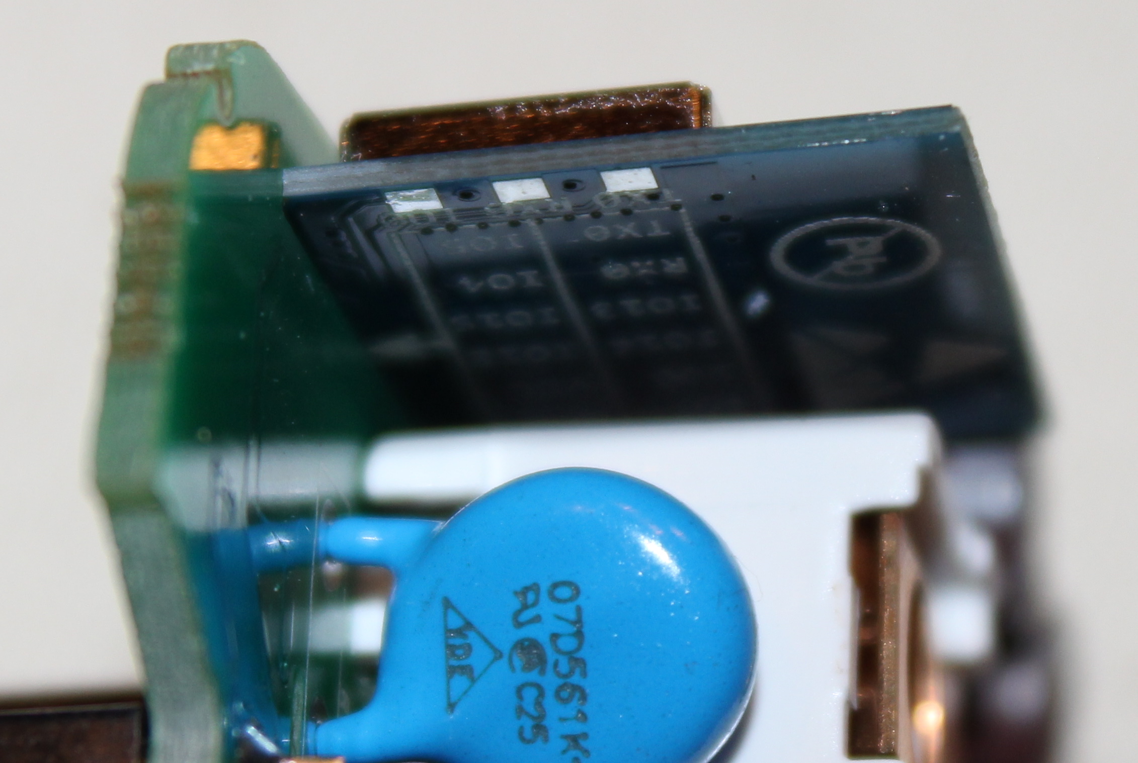
I have to solder a wires to the 3.3V, GND, RX, TX and GPIO0 pin in order to connect it to a usb to serial converter. It doesn't matter if I choose the pins on the one or the other side of the module as long as they match the pin I want.


Now I connect the wires to the usb-serial converter. The RX and TX wires have to be crossed. Most important is to use 3.3V and not 5V or you might fry your esp module :wink:
(GPIO0 wire is missing in this picture)

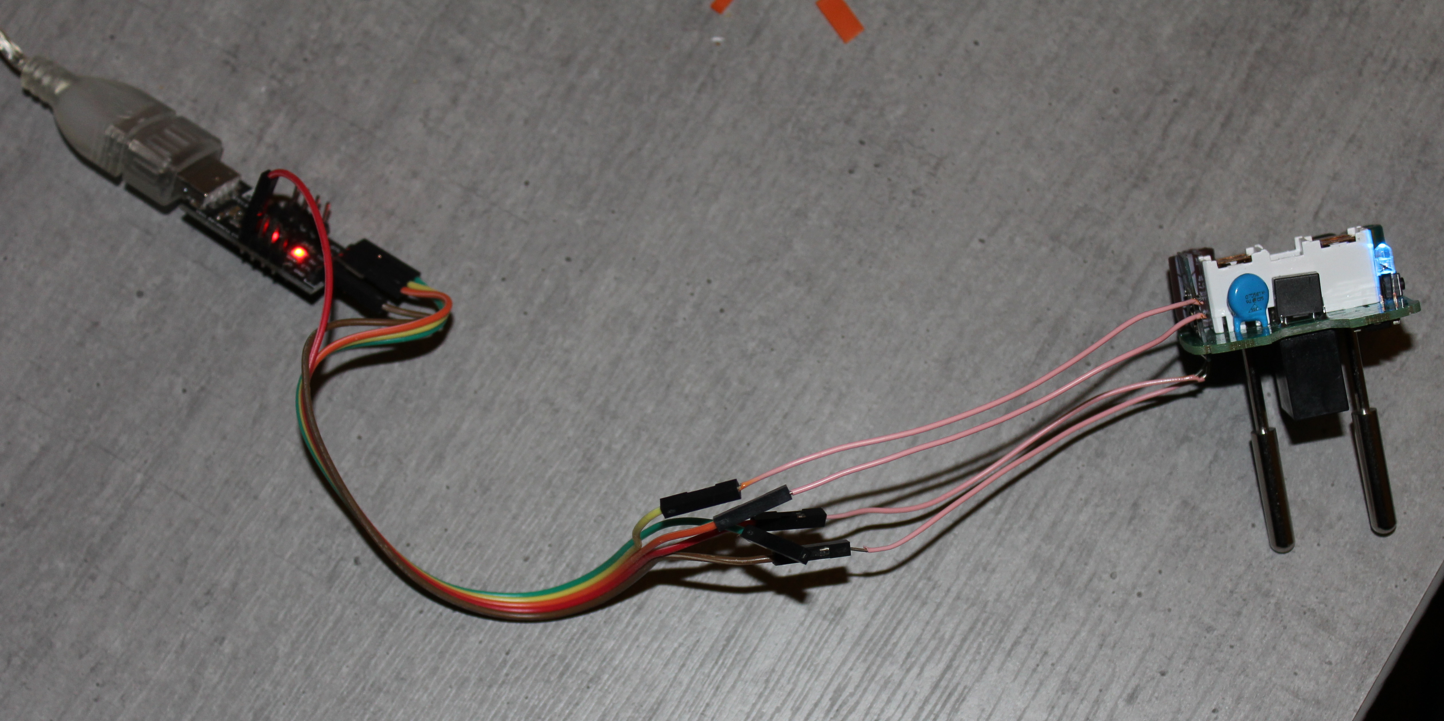
After powered on by the converter the led starts blinking. The esp module is running its stock firmware.
Now I set the module into flash mode by connecting GPIO0 to GND (disconnect the converter from usb before that)

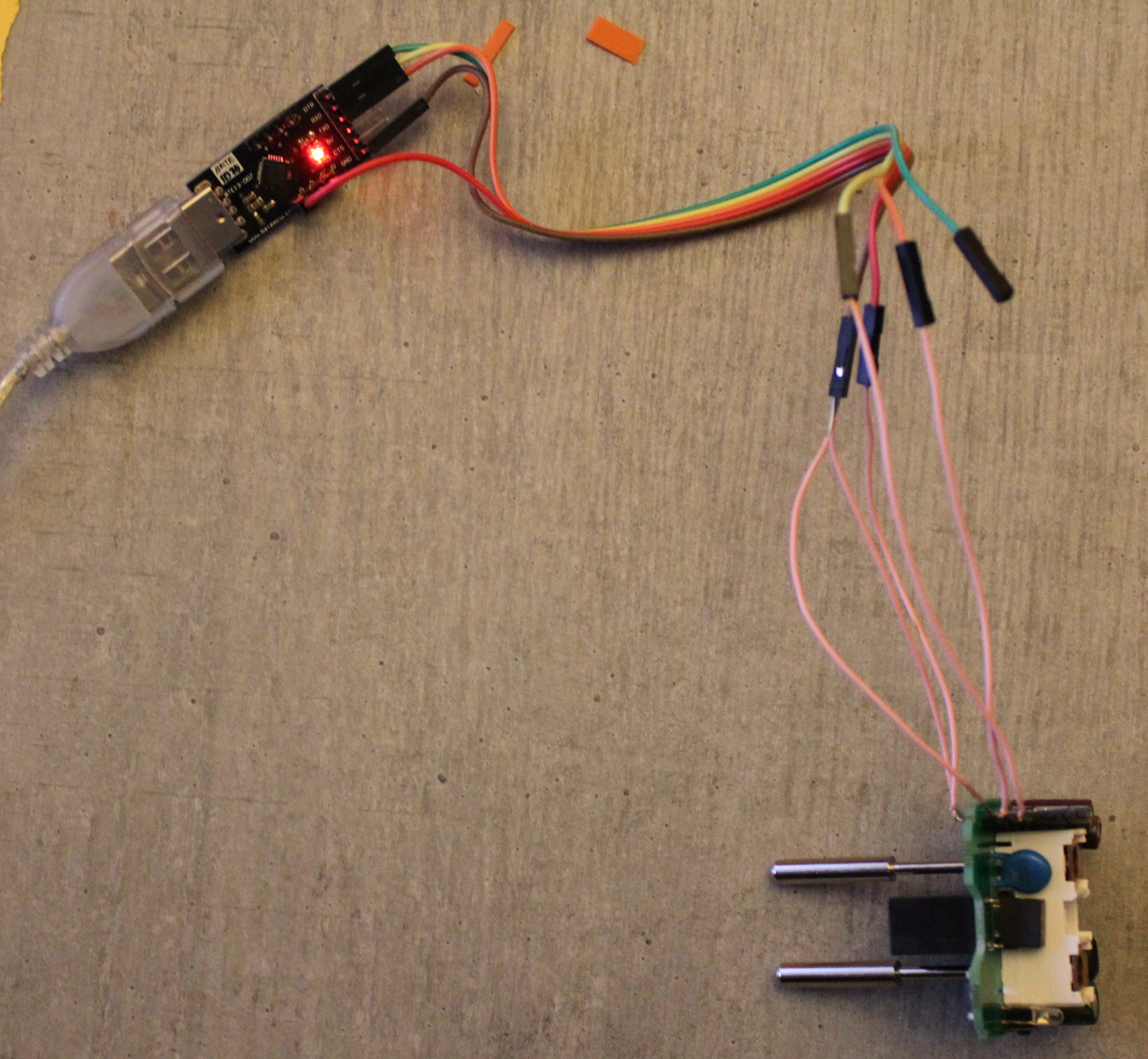
and connect the converter again. This time the led doesn't blink. Disconnect GPIO0 from GND after like 10 seconds. Now everything should be ready to be flashed.
As flashing tool I use NodeMCU-PyFlasher-4.0. Configure it like I did (COM port my vary)


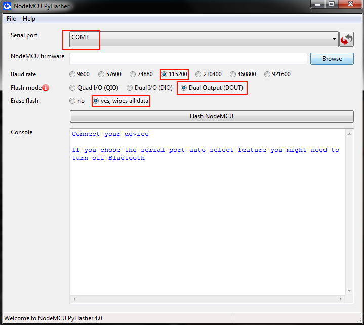
Download a firmware with your favourite language here, load it and flash it
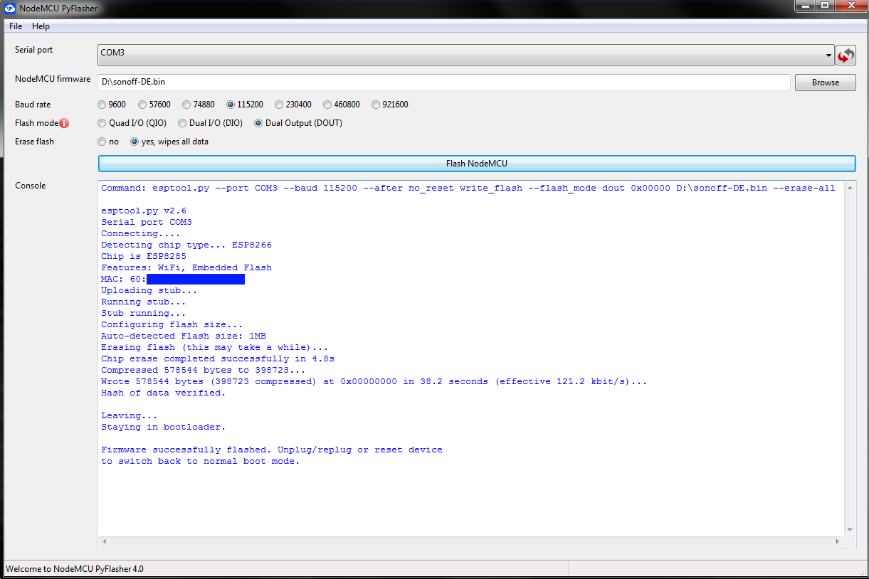
 :slight_smile:

And that's it :slight_smile: The plug is now running on Tasmota firmware.

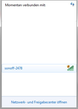
Now you can connect the plug with your wifi.
Search with your smartphone or laptop for a new wifi with sonoff in the name and connect to it.
sonoff_wifi
Now open your webbrowser and let it connect to the wifis login page


search for your home wifi and enter the password and click on save. The plug should now be connected with your wifi.
Check for the ip of the plug on your router and then enter it into your browser.
You should be welcomed by this

The following configuration is specific to this device.
Click on configuration -> configure module. Change the device typ to generic and save it. After the device rebooted set the following pins:


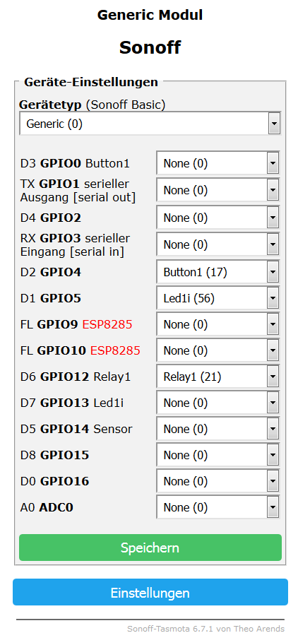
I found the used GPIO pins by following the traces on the pcb to the led and the button. First the led didn't work as it should so I changed it to the inverted led option (Led1i)

Now we just have to desolder the wires and assemble the plug again

aaaaaaand done :slight_smile:

allfolks

Special thanks to @foosel. She provided assistance while I was doing this :slight_smile:

5 Likes

reserved 1234567890

reserved 0987654321

I was seeking for that - and I'm eased to find it. Maybe you highlight this, it's vital. :sunglasses:

1 Like

Done :slight_smile:

I wrote this part as last step because if anything goes wrong it's no problem to flash it again

I also added a warning at the top

1 Like

you can flesh those without opening them

check out: https://github.com/ct-Open-Source/tuya-convert

2 Likes

Do you know any other such companies? I'm looking for a specific one that makes switches like this:

Those are touch pads for the switches, unlike the clicky ones that I see on Tuya.

I'm using these: http://www.wifioprema.rs/product-category/ceo-asortiman-wifi-opreme/

they are touch pads, not clicks :smiley: as you want
inside is esp and you hack them just like tuya with tuya-convert app so you can upload firmware without opening them and soldering pins on to 8266 board...

most of those boards you can hack with tuya-convert even when they have nothing to do with tuya :slight_smile: the hack works for most of those esp8266 based devices

1 Like

Thanks.
That's a solution for certain cases.
You need an unpatched plug, and you have to know which GPIO ports are in use. I mean sure you could test all ports for a normal or inverted led but yeah.. :smiley:
I think it's easier to follow the traces on the pcb - especially if you have screwed case.
Also I plan to add some modules like a 433 MHz transmitter and a DHT 22 sensor (because why not :smiley:).
So I have to open them anyway :slight_smile:

If you have a known plug and don't want to mod it your way is probably the best solution.

No sorry I'm new to this stuff :slight_smile:
I would try to assaign them as buttons

well I use many of these, first one I disassembled to see what gpio's are used and what's inside at all ... but for the rest of them I just reflashed them without opening :smiley:

the only issue I have (with switches, not with sockets) is that they require neutral to be there too (normally in socket you have live in and N output's for lights, there's no neutral in the socket and all the switches I tested require one) ... I was thinking of making my own switch that does not require neutral (to put a small liio pack inside and charge the pack trough the lightbulb while light is turned off) but gave up, I need so many of those (renovating new 450 m2 house) so I decided to just wire neutral to the sockets as well as I need to do the wiring from scratch anyhow

for adding sensors, yes, that's something else completely, but I have independent sensor network on xbee attm that I'll probbly completely redo for the new house... not really a octoprint topic so..

2 Likes

You can post offtopics at the General category and also show us your smart home here at Showcase if you want :slight_smile:

:slight_smile: well there's no smart home yet... I live in appt where nothing is smart (I do have few wireless switches and few wireless sockets and a sensor network but is all related to different projects, not really a smart house), I do have tested a bunch of stuff I do plan to setup in a house I purchased recently that I'm renovating for 6 months already and there's at least another 10 months left and there I plan to setup a full smartness I can come up with (as that's, hopefully, my final house :smiley: ) ... I wanted to go PLC way but gave up as I could not find a good PLC module that does not cost arm & leg, then I looked at hooking it up on some custom mesh (xbee or nrf or ...) but I found so many bugs in those systems that there's no way in hell I'm gonna put it in my house... so I ended up deciding to go with esp (both 8266 and 32) using insecure wifi (as seems like WPA/WPA2 are not more secure than WEP :frowning: ) but with a custom layer on top that will provide security.... after I'm done I'll post the whole story somewhere (probbly on my elco blog if I get it out of the grave, clean from viruses and put back online - fscking wordpress got hacked) and will link here too :smiley: .. but I doubt it's very useful to link stuff totally unrelated to printing to octoprint forum... even in showcase space :smiley: ... (your post is ideal for showcase, I didn't want to be obstructive, just wanted to share a link to a tool many don't know exist that can be used to flash all those esp based devices without opening them, as when you wanna tweak one, it's cool, but when you want to tweak hundred it's pita... but a post about smart house, unless bunch of stuff for that is 3dprinted I doubt is a proper one)

now, wrt pinout I think tasmota have template for the ones you are using :smiley:

check out:
https://blakadder.github.io/templates/AWP08L.html

{"NAME":"AWP08L","GPIO":[0,0,56,0,0,0,0,0,0,17,0,21,0],"FLAG":0,"BASE":18}

1 Like

Well done!

Honestly, I'm considering pirating all my Amazon-based devices (Echo, Spot) since I don't 100% trust them anymore (with their fondness for turning back on the eavesdropping aspect). If I do, I'll add to the write-up.

And then again, there's the painfully-stupid Windows-based media control panel in my car's dashboard. <_<

1 Like

That didn't work for my plug - all GPIOs are wrong.

Here is my template

{"NAME":"WSIIROON","GPIO":[0,0,0,0,17,56,0,0,21,0,0,0,0],"FLAG":0,"BASE":18}

That would be great :slight_smile:

Pull a neutral from the panel!. Apparently it's not hard.

well in this appartment where I live attm is hard, they are not using the channel/tubes between junction boxes and the switches so I have ~1.5m of wall I'd need to dig a channel in to put the neutral from the junction box to the switch (not sure if I'm using proper English terminology for this, the live+neutral+ground comes to the junction box that's near the ceeling, from junction box live comes down to switch, normally trough a plastic pipe, but not in this appt, and then a 1 or 2 or 3 wires return to the junction after the switch, then from junction neutral and ground go directly to lights and the 1/2/3 wires from the switch go to the lights as live. In this appt the cables sometimes come to junction trough plastic pipes, sometimes they are just in the wall channel and mortar is on top so no way you can pull another wire there, and everywhere the switches are connected to the junction without tubing so impossible to pull another wire... In the house I'm redoing it all so will not be a problem, I even originally intended to pull a phone wire, the famous "blue/white" 1.8mm copper wire to every single switch & socket as a "data line" but gave up)

Perhaps you should try making your own again. Are you aware of this phenomenon?

1 Like

of course :slight_smile:
that's what I was about to be using to charge my liio pack for my switch that does not require neutral, but since I was informed that we need to redo the wiring in the house I gave up on the project as it will be simple to bring a neutral to the switches now..

1 Like

Don't give up. Somebody somewhere might need your solution :wink:

Any metal water pipe in your apartment by regulation should be well-grounded, for what it's worth.

1 Like