PSU Control relay won't switch

Hi,

I need some help to switch my relay.

I have 2 3.3v relays like this https://nl.aliexpress.com/item/1PCS-1-Channel-Relay-Module-Optocoupler-Isolation-3V-Blackboard-BESTEP/32815654145.html?spm=a2g0s.9042311.0.0.ed574c4dqAkS1e (Bought from different sellers)

Now I connected the VCC to 3.3v pin 17
GND to pin 20
and IN to GPIO24 on pin 18

I set PSU Control plugin to Board and GPIO control the selected pin 18
Though when switching with the nav bar button nothing happens on the relay.
I do have a solid red light on it and and then swapped GPIO pins with same results.

after that I swapped relay to the second one I have.

also tried to power the relay from 3.3v on breadboard and still not switching when i put 3.3v on the IN connector.

Measured 1.3v between GND and IN.

any help would be great,

Jasper

Normally, I personally buy the relays that have two sets of jumpers. One set usually has "JD-VCC | VCC | GND" & the other set has "GND | IN1 | IN2 | VCC" (or more or less INx pins). Yours just appears to have one bank with "VCC | IN | GND". Usually, the 'control' circuit runs off the +3.3v line & the 'relay' switch circuit runs off the +5v line. The purpose of the "JD-VCC | VCC" is to cross-wire the two power lines. From a Raspberry Pi perspective, this cross wiring usually doesn't work because the +3.3v line doesn't have enough ooomph to flip the switch in the relay circuit (this means pull off the jumper that cross-wires JD-VCC to VCC, which is the blue one in my pic, or you're dead in the water).

All the advice that I can give for the ones that you bought is to try connecting the +5v instead of the +3.3v line to VCC.

If that doesn't work, I fear that you're out of luck.

For the record, the only way that I have got these kind of relays to work flawlessly is to connect them like this (providing you have the two blocks of jumpers, that is):

Block of 3 pins

JD-VCC to [+5v]
VCC to [+3v3]
GND to [Ground]

Other Block of pins (with one or more INx pins)

IN1 to [GPIO4 (any GPIO will do though]
IN2 to [GPIO17 (likewise, any GPIO will do]
VCC & GND have already been connected on the other block, so you can completely ignore them.

You really should try getting it running from a command line first. Just type in gpio & if you're in luck, it will say "gpio: At your service!" All of these relays have switches that make a loud "Click" noise & a little red LED that turns on/off, so you don't need to have anything connected to them to tell if they're working - you can just look & listen.

I use GPIO17 (which is pin 11 on my very elderly Pi B) [note: are you using the right physical pin for your GPIO on your Pi? The physical pin number & the GPIO number are completely different!)

Try:

gpio -h
gpio export 17 out
gpio -g write 17 1

gpio -h -> tell me what all the functions do
gpio export 17 out -> set GPIO pin 17 to be an output
gpio -g write 17 1 -> 1 to set it high, 0 to set it low

The "-g" tells it what type of numbering scheme I am using. Look this up, as it'll really help.

s-l500

I buy my Relays from eBay, but I make sure that I carefully study the photos to check that it's got the two banks of pins & particularly the JD-VCC one before I click "Buy". I think it cost me 99p, so I didn't exactly spend big bucks :slight_smile:

U power the relay with 5V. Don't use the pi 5V pin. The signal pin is 3V tolerant so use GPIO for that. All your grounds need to be tied together. Please be aware that the pi GPIOs aren't especially tolerant to a lot of current. Luckily, the signal pin on all these relays are just looking for a voltage and draw is minimal. Just don't try to power it from the pi. Use another 5V power source.

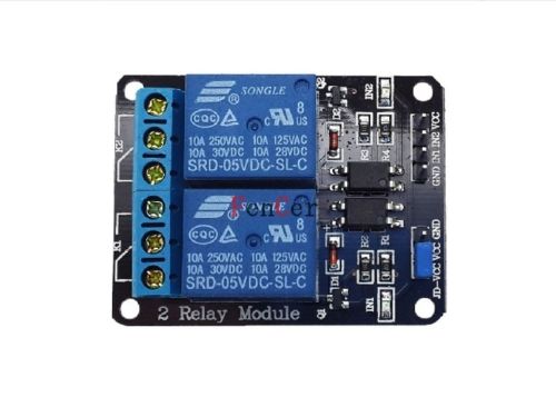
It depends on what kind of PSU you're using. Assuming that it's a std PC PSU, I made a video of what I did, using the relay you listed along with the PSU Control plugin

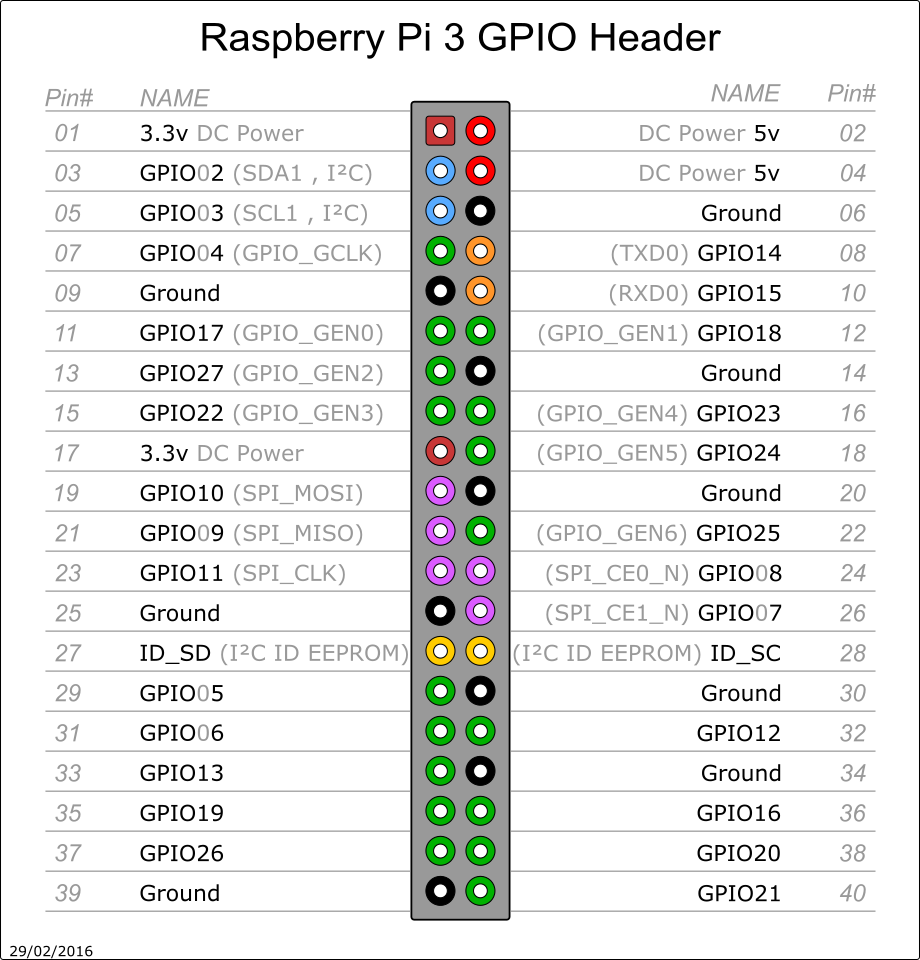
First of all, the pin numbers can be confusing if you've never messed with them before...

Now, if you look on the left side, you'll see where it says "Pin#". That's the "Board Pin"
The next row that says "NAME" is the "Broadcom Pin" assignment
Then the next row isn't labeled, that's what the plugin refers to as "GPIO Pin"

As you can see, many of the pins have 2 and some have 3 name assignments, so you have to know which you are trying to use. The code you use will determine that

Looking down the left side, I'm using "Board Pin#'s" 11 and 13, which is "Broadcom pin" numbers 17 and 27

Now, in the PSU Control plugin, there is a drop down box to choose between "System Command", "GCODE Command", and "GPIO PIN"

If you choose "GPIO PIN" 17 and 27 translates to GPIO0 and GPIO2, for which the code would be...

#!/bin/sh

gpio write 0 1 && gpio write 2 1

This writes a "1" to pins 0 and 2, and turns them both on. A "0" would turn them off

Now, if you want to use System Commands (which is the "Broadcom #'s), the code would be...

#!/bin/sh

echo "1"> /sys/class/gpio/gpio17/value
echo "1"> /sys/class/gpio/gpio27/value

Again, writing a "0" would turn them off

Also, the suggestion to test them first is sound. Just create those scripts for the proper pins, and execute the script, and see if the relay "clicks". You'll hear it

Here is the video instructions of how I set up my relay thru the pi

Admittedly, I used a HAT to segregate the signals cuz I have mine connected to Alexa, but, the commands are still the same

I know it's a bit wordy, but, I didn't want to leave anything out. Hope it helps

Thanks,

I'll have a look at powering the relay or get another one for the project.

So as I understand, the Pi always keeps powered on unless I do not completely switch of the ATX PS, yes?