Hey there! Developer of OctoPrint WS281x LED Status here. I have been working on this plugin for nearly two months, and it's been on the official repo for nearly a month now.
I have had some great feedback from users, but I wanted to see how people had set it up, so here we are!
If you are using my plugin, post a picture below of your setup!
I am just getting through setting up my 2nd strip, so I can keep the other specifically for development. Once it is done, I'll join in!
You can also use this thread for a general chat, or any questions that you have. Maybe you don't have an LED strip yet, and want to find out how easy? Or got a question about how to use a particular feature? I'll help out as much as I can.
Enjoying the plugin? You can support my work here from as little as $1
2 Likes
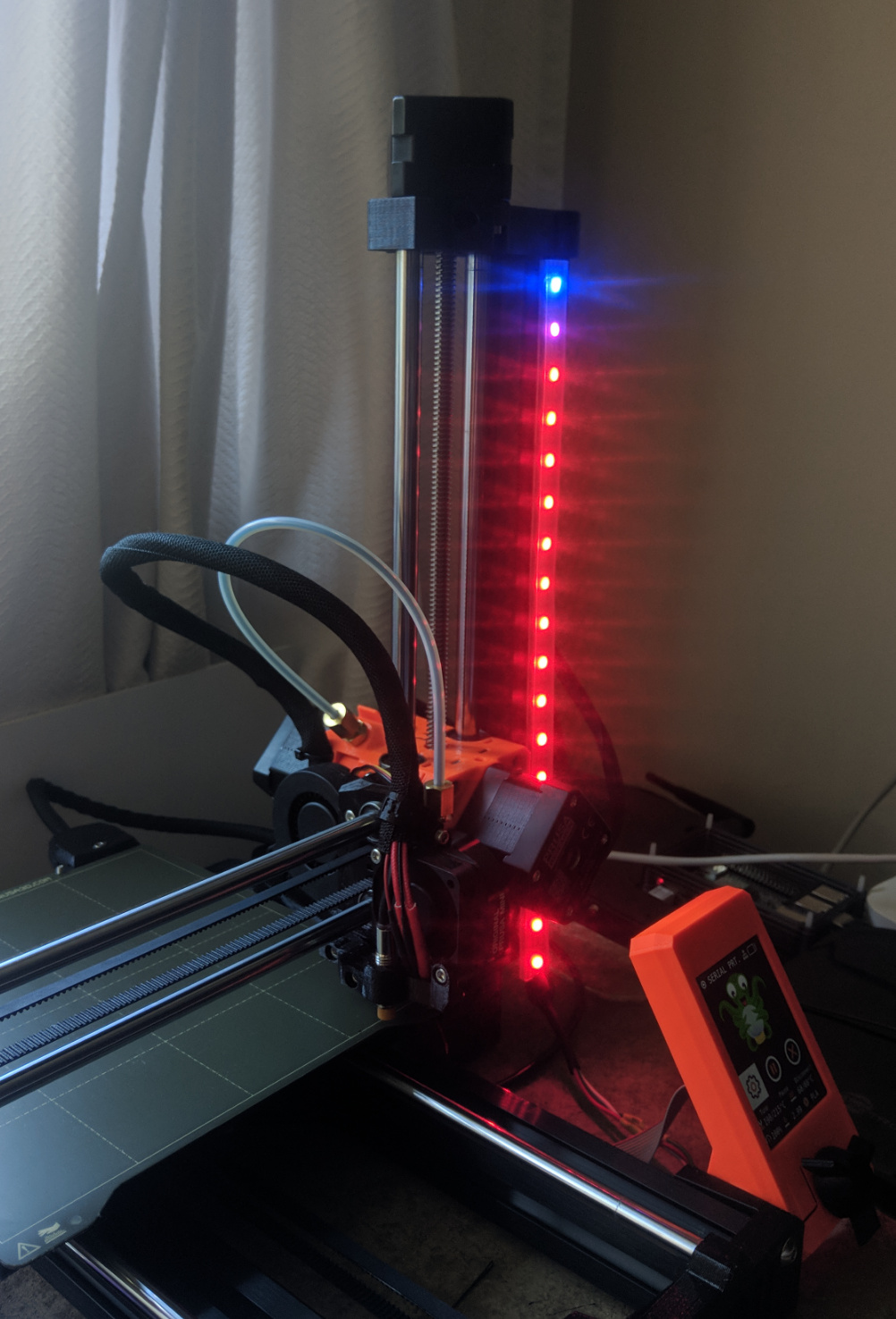
Here's my current hacked-together setup on the printer...
1 Like
Great plugin (not so great photo!), thanks for all your hard work!
1 Like
Great placement for the Prusa Mini. I'm debating whether to mount mine horizontally or vertically on my Ender 5 Pro coming this week. Should look a lot nicer than the taped together setup above.... I like seeing what people do with it! Enjoy.
Thanks  I was planning something different but saw this design https://www.prusaprinters.org/prints/39674 to clip into the extrusion and thought it would work, at least until I build some form of enclosure for the printer.
1 Like
Is there a way that you can make it were i can control the neopixels on my board not the rpi like it will send the m150 instead of controlling gpio?
No, that's not possible with the plugin, and its too tailored towards the RPI GPIO to add it as a feature. You would also be very limited to what you could do with that, since it would be a choice between (a) solid colours, or (b) spam the serial connection for each individual LED. Not a great idea when idle, let alone when printing, so I think that is best left up to the firmware.
For onboard control I would look into this plugin.
1 Like
Hi,
great work! I really like this plug in and it is working well. Only if i try to use the test buttons. There is no reactions. Do i have to do something special before like unchecking something..?
thanks for your help!
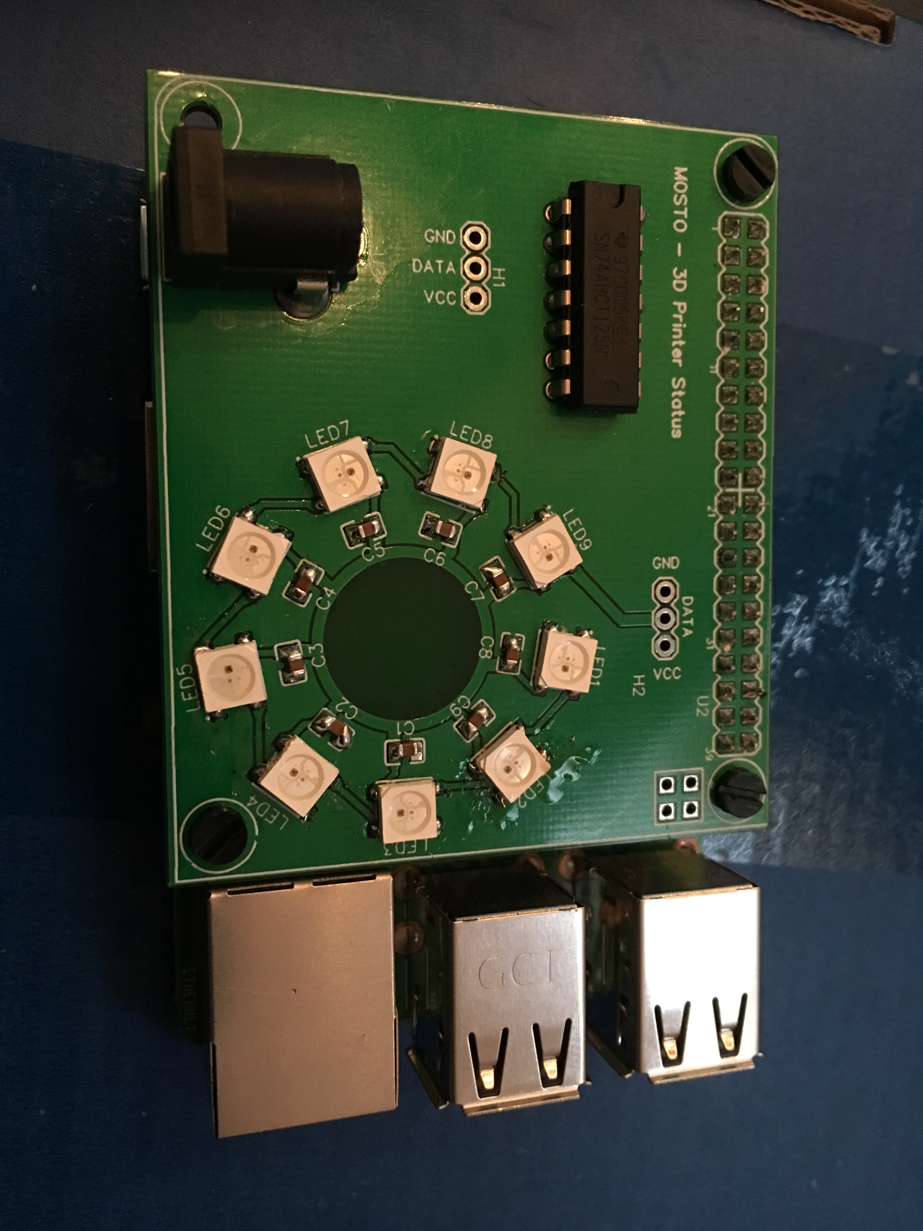
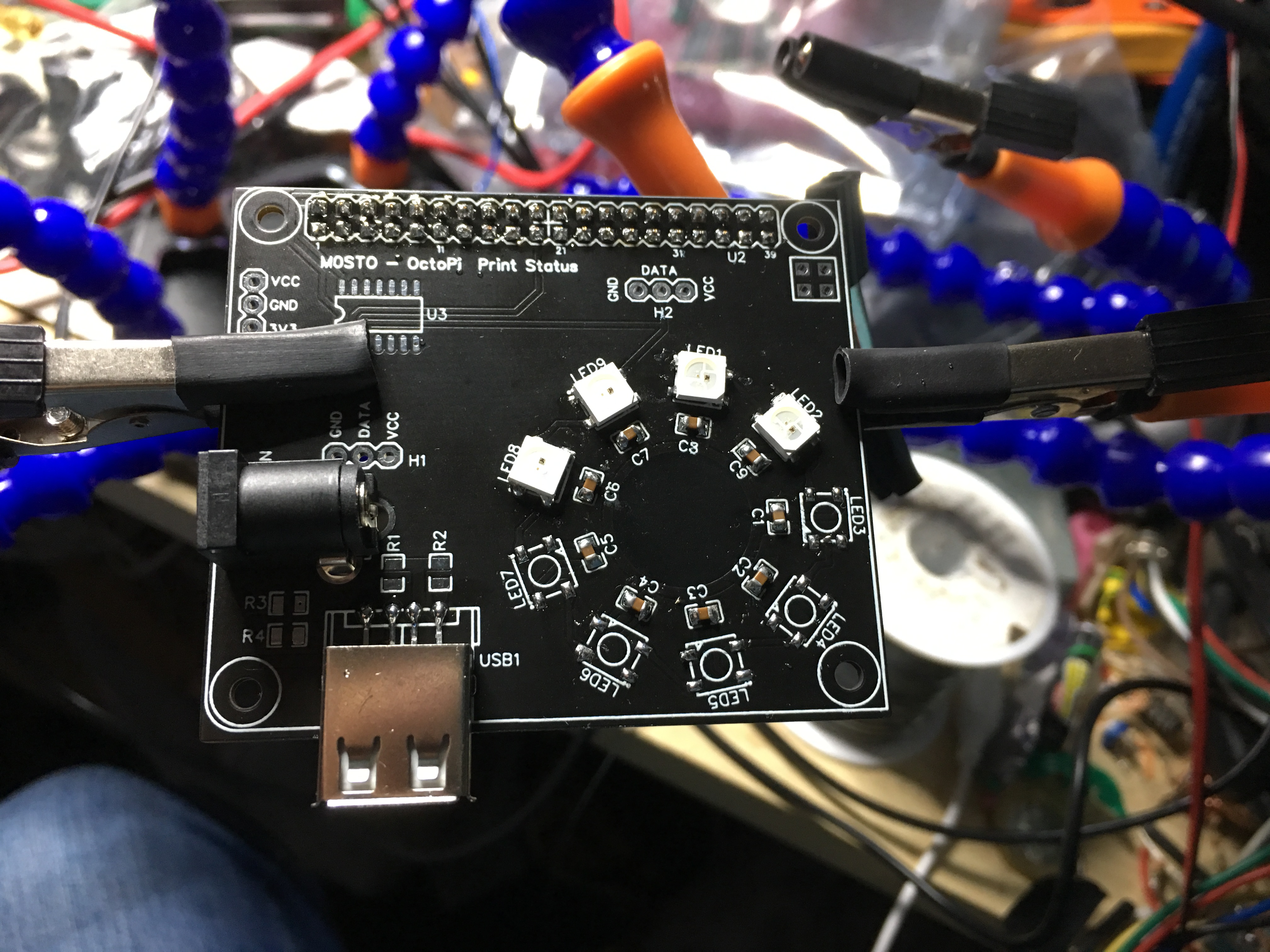
I created a HAT for the Raspberry PI and I'm going to refine the HAT to all SMD components. I will send the publisher the Gerber and schematics for review and then whoever wants to download them can make them at will. Some SMD soldering or reflowing will be required. Please note this is the first design where the board is powered externally. The second version will contain a USB socket that will power the HAT, LEDs and the Raspberry Pi from a short USB A to Micro USB cable. This will increase the overall current permissible to 4 amps. Enough to drive most arrays. The onboard LED's can be omitted for strips and holes have been provided.
All the best. Creatlity CR10 V2, Raspberry Pi 3 B+. Latest version of OctoPi and WS281x plugin.
1 Like
I'm confused by this statement. The RPi 3 (& 4) have a micro USB (or USB-C) socket and require 2.5-3 amps. If this hat is designed to power itself, the RPi, and LEDS with a 4 amp max, that leaves approximately 1 amp for the LEDS which, IMO, isn't very much.
1 Like
@CodfishCatfish That's cool! I took a go at designing a custom mini hat for my LEDs, but there were several things wrong with it that needed fixing after manufacture that it was not good enough to share...
If you have somewhere with the files and an explanation I could link to it from the plugin's page. And maybe re-design my own and create a collection of add-on boards.
@b-morgan From my experience these kind of addressable LEDs use ~40mA each, can up to 60 on full white 100% brightness. So total this would be 360mA (Max 540mA) so 4A for Pi + LEDs should that should be enough. I'm currently using 2 separate 3A supplies, but I think using just one would be a good design in the furture.
Hey @Lichtprotos, apologies I must have missed responding to this (Maybe never pressed send...!)
For the LED test to work, the printer must be connected, and M150 intercept needs to be enabled in the settings. There is work going on to reduce this dependency (&use the API instead) in the future.
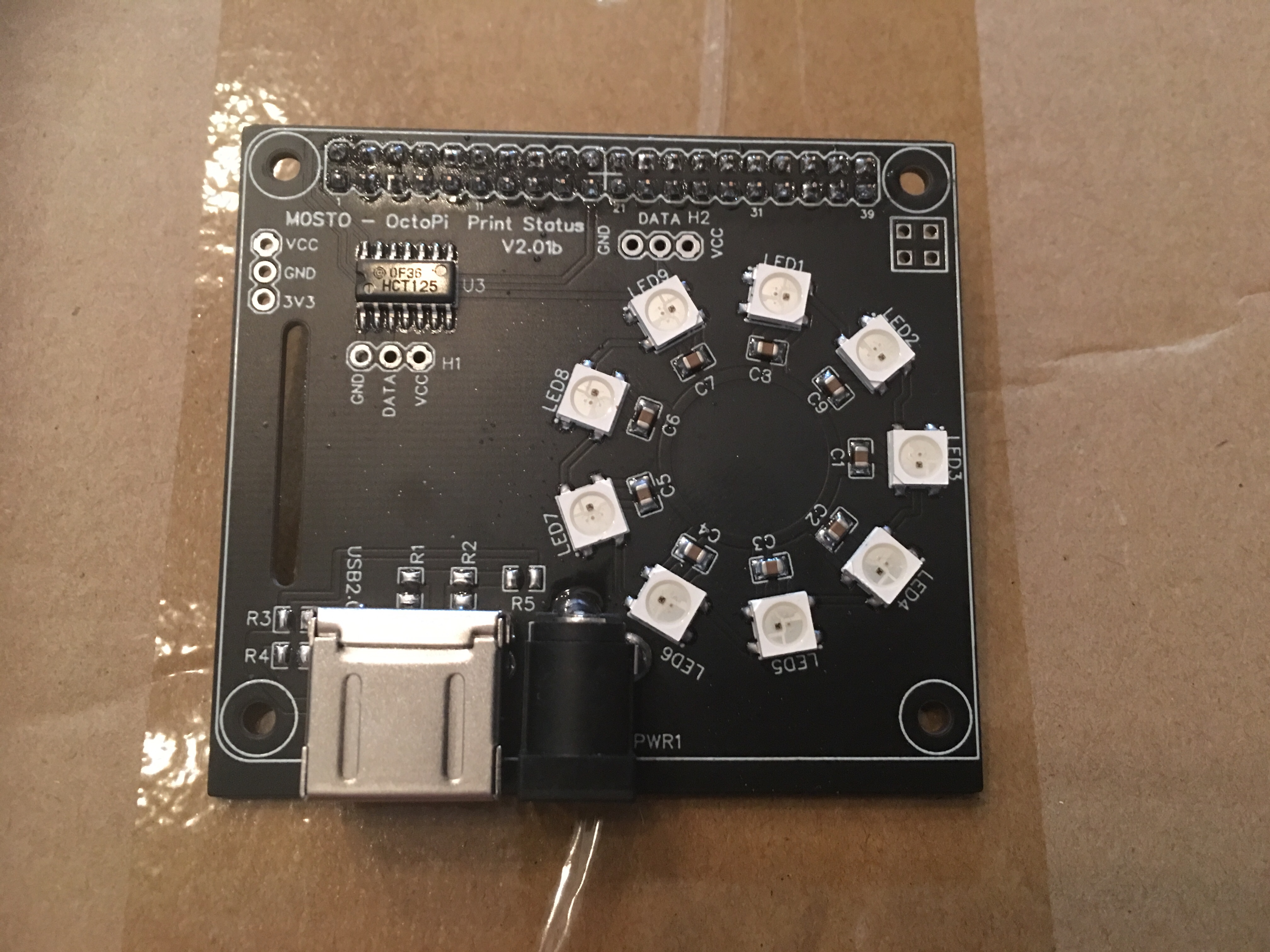
Hi, the statement is correct but I see how it reads like mud. You can supply any number of LEDs you wish and just updating the power supply would be enough but would use caution as the tracks aren’t designed for that high current. ( I wasn’t expecting elaborate arrays of 144 LEDs). Basically as stated the version 2 will have a 2.5mm / 5.5mm D.C. socket which will handle 5amps if required. The HAT will also have a USB A socket so that a simple short USB A to Micro USB or USB A to USB C. With a USB socket you can power other devices if you wish rather than excessive current powering the LEDs only. Also USB C on the Pi 4 is know to have issues with certain PSU’s and not power. I believe Raspberry PI know of this and are correcting it or there would be different connector. For now you can use 10amp PSU and power just the LEDs but why not power the Pi as well and cut down on many PSU’s. In tests I found that on 50% brightness and all LEDs on white (9 x 30ma) still only drew about 280ma which is far less than 1amp. Anyone who needs these LEDs on full white 100% brightness all the time (torch mode) then should wait for v2 which will be refined to handle higher currents. This is merely v1 for proof of concept and make it idiot proof and plug and play. I had contemplated using the PI’s pins but I’m big on Arduino and that normally means bypassing the onboard regulator hence the Pi powers the IC separate from the LEDs so even at full brightness the PSU is doing the hard work and NOT the Pi’s regulator. It’s so ultra basic but it’s how I start all my projects. Proof of concept, prototype, v1. Then redesign from scratch Open the concept for many interfaces eg: Pi3 or Pi4 then v2. I’m actually working on v3. Now which will have USB3 and QC circuitry but alas is wont fit on the HAT, even double sided. v2 actually has spare pads for resistors to act like a phone charging USB wall wart. This was originally so I would charge a phone at full capacity too using a double USB socket and the bottom for Pi and the top for a phone. I dropped that idea and went with single height and left the pads in for fun. This is probably why I produce about 30 prototypes a year and only 10% finish up as completed projects? The prototype is normally that good that it’s hardly worth going all out on a redesign. As you can see there is a USB socket as power out and 2.5mm for power in on the image below of v2 but v2 is probably going to remain as is due to supplier of my USB sockets and footprint errors. I’m halfway through assembly. I doubt it will progress so perhaps v3.
Kind regards Spence! image|666x500
1 Like
Hi Charlie. The prototype in my opinion is wasteful of space and Power refinement but no problem with a write up and Gerber files. I think the schematic is in my usual here, there and everywhere format so won’t include that. If someone is interested in it then it’s about £5 ,€6 or $6 worth of parts. The problem is the boards cost £8 including shipping for 5 (minimum order). So it’s possible to still produce the board for £5 but you would have to split the costs of the PCB with friends. Please allow me a day or two as it might be worth waiting for v2 over v1.
Kind regards spence
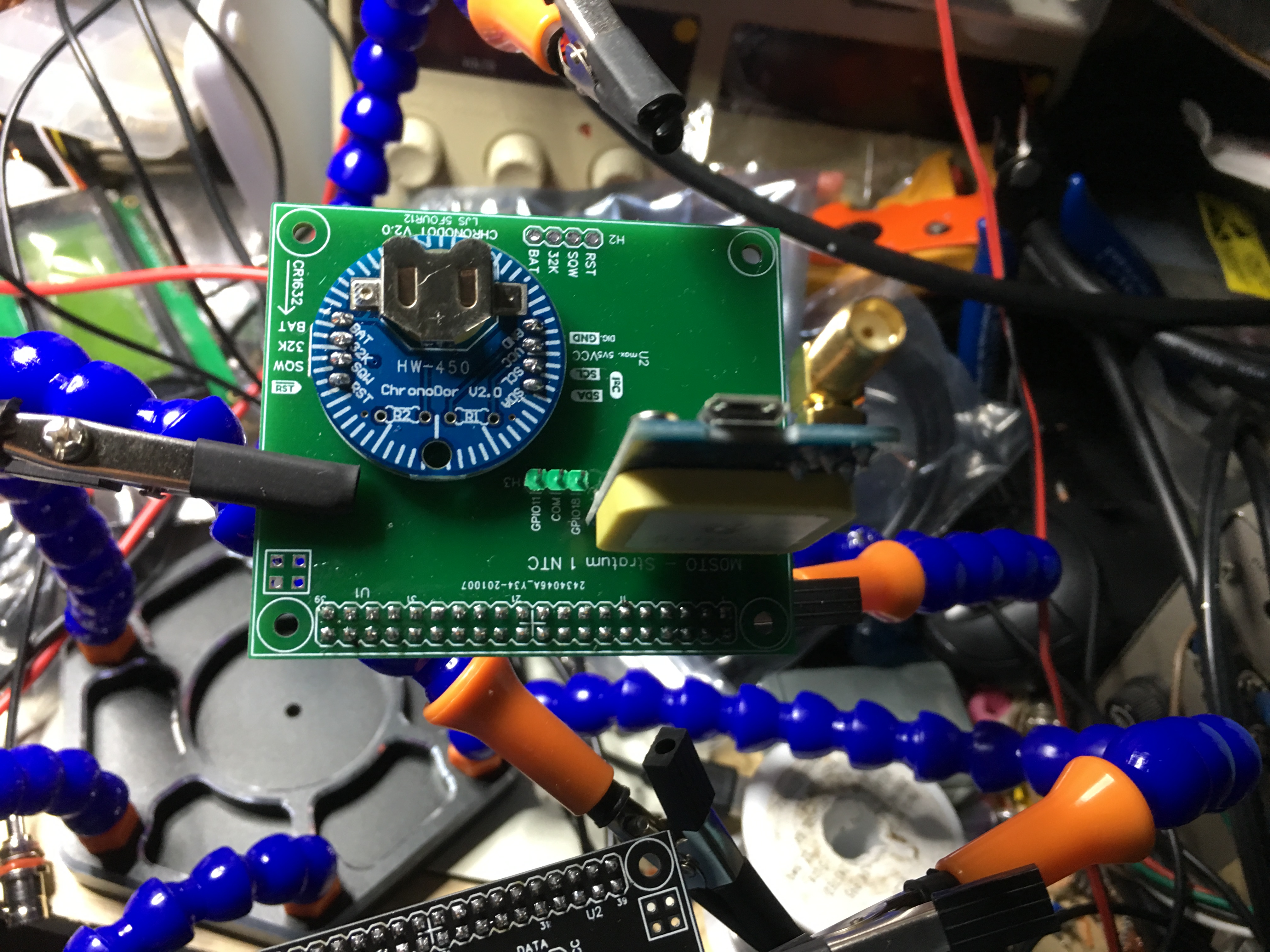
Talking of add on boards my ultra basic Stratum 1 NTC server below...
I'm nearly finished setting up my version of LED status. Was wondering if there is a way to have it sync w/ Octolapse - so that when a picture is taken, LED's go full bright white?
I've made a Lack table enclosure w/ a homemade lack table, with increased height. Running WS2812 lights on the top of the enclosure, and along the z axis support rails for my Monoprice maker select. Main goal is decent lighting for time-lapse images, but do desire the status lights throughout the enclosure.
How would I go about commanding it so that when Octolapse moves carriage for timelapse photo, full white bright is enabled on all LED's?
Thanks!
1 Like
Does octolapse have options for running gcode commands prior to and after the snapshot? If so you could utilize this.
Yeah, looks like octolapse has custom camera scripts which includes before snapshot gcode and after snapshot gcode. You can use the gcode support of the ws281x plugin with the M150 commands in there.
Thanks @jneilliii - yep, I would say a combination of the M150 gcode, and the @ commands will get you there. M150 if you want it a custom colour, but the downside is it wouldn't resume the status. You can use use either of the torch modes too with the @ commands - but if you use toggle mode, be sure to turn it off again afterwards!
Dear group, this is the probably the last incarnation of the status (unless someone specifically ask me to do something). I will send the Gerber files to Charlie and he can decide when to release them. I do have one more mod that includes a reverse protection diode and a resettable PTC or positive temperature coefficient fuse rated at 3a hold current and 5a trip current which is loads of room for some of the more demanding strips. Anywho enjoy...!
1 Like
