Hey @Lichtprotos, apologies I must have missed responding to this (Maybe never pressed send...!)
For the LED test to work, the printer must be connected, and M150 intercept needs to be enabled in the settings. There is work going on to reduce this dependency (&use the API instead) in the future.
Hi, the statement is correct but I see how it reads like mud. You can supply any number of LEDs you wish and just updating the power supply would be enough but would use caution as the tracks aren’t designed for that high current. ( I wasn’t expecting elaborate arrays of 144 LEDs). Basically as stated the version 2 will have a 2.5mm / 5.5mm D.C. socket which will handle 5amps if required. The HAT will also have a USB A socket so that a simple short USB A to Micro USB or USB A to USB C. With a USB socket you can power other devices if you wish rather than excessive current powering the LEDs only. Also USB C on the Pi 4 is know to have issues with certain PSU’s and not power. I believe Raspberry PI know of this and are correcting it or there would be different connector. For now you can use 10amp PSU and power just the LEDs but why not power the Pi as well and cut down on many PSU’s. In tests I found that on 50% brightness and all LEDs on white (9 x 30ma) still only drew about 280ma which is far less than 1amp. Anyone who needs these LEDs on full white 100% brightness all the time (torch mode) then should wait for v2 which will be refined to handle higher currents. This is merely v1 for proof of concept and make it idiot proof and plug and play. I had contemplated using the PI’s pins but I’m big on Arduino and that normally means bypassing the onboard regulator hence the Pi powers the IC separate from the LEDs so even at full brightness the PSU is doing the hard work and NOT the Pi’s regulator. It’s so ultra basic but it’s how I start all my projects. Proof of concept, prototype, v1. Then redesign from scratch Open the concept for many interfaces eg: Pi3 or Pi4 then v2. I’m actually working on v3. Now which will have USB3 and QC circuitry but alas is wont fit on the HAT, even double sided. v2 actually has spare pads for resistors to act like a phone charging USB wall wart. This was originally so I would charge a phone at full capacity too using a double USB socket and the bottom for Pi and the top for a phone. I dropped that idea and went with single height and left the pads in for fun. This is probably why I produce about 30 prototypes a year and only 10% finish up as completed projects? The prototype is normally that good that it’s hardly worth going all out on a redesign. As you can see there is a USB socket as power out and 2.5mm for power in on the image below of v2 but v2 is probably going to remain as is due to supplier of my USB sockets and footprint errors. I’m halfway through assembly. I doubt it will progress so perhaps v3.
Kind regards Spence! image|666x500
1 Like
Hi Charlie. The prototype in my opinion is wasteful of space and Power refinement but no problem with a write up and Gerber files. I think the schematic is in my usual here, there and everywhere format so won’t include that. If someone is interested in it then it’s about £5 ,€6 or $6 worth of parts. The problem is the boards cost £8 including shipping for 5 (minimum order). So it’s possible to still produce the board for £5 but you would have to split the costs of the PCB with friends. Please allow me a day or two as it might be worth waiting for v2 over v1.
Kind regards spence
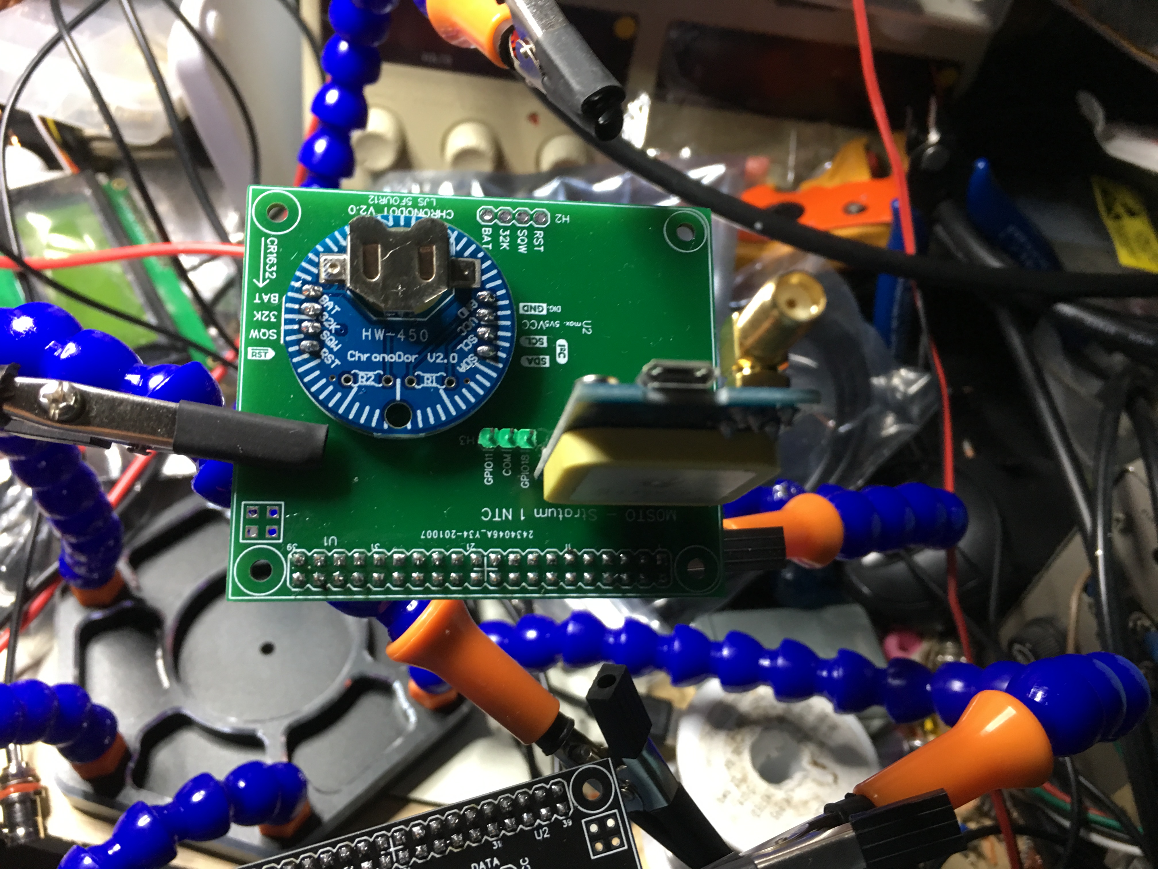
Talking of add on boards my ultra basic Stratum 1 NTC server below...
I'm nearly finished setting up my version of LED status. Was wondering if there is a way to have it sync w/ Octolapse - so that when a picture is taken, LED's go full bright white?
I've made a Lack table enclosure w/ a homemade lack table, with increased height. Running WS2812 lights on the top of the enclosure, and along the z axis support rails for my Monoprice maker select. Main goal is decent lighting for time-lapse images, but do desire the status lights throughout the enclosure.
How would I go about commanding it so that when Octolapse moves carriage for timelapse photo, full white bright is enabled on all LED's?
Thanks!
1 Like
Does octolapse have options for running gcode commands prior to and after the snapshot? If so you could utilize this.
Yeah, looks like octolapse has custom camera scripts which includes before snapshot gcode and after snapshot gcode. You can use the gcode support of the ws281x plugin with the M150 commands in there.
Thanks @jneilliii - yep, I would say a combination of the M150 gcode, and the @ commands will get you there. M150 if you want it a custom colour, but the downside is it wouldn't resume the status. You can use use either of the torch modes too with the @ commands - but if you use toggle mode, be sure to turn it off again afterwards!
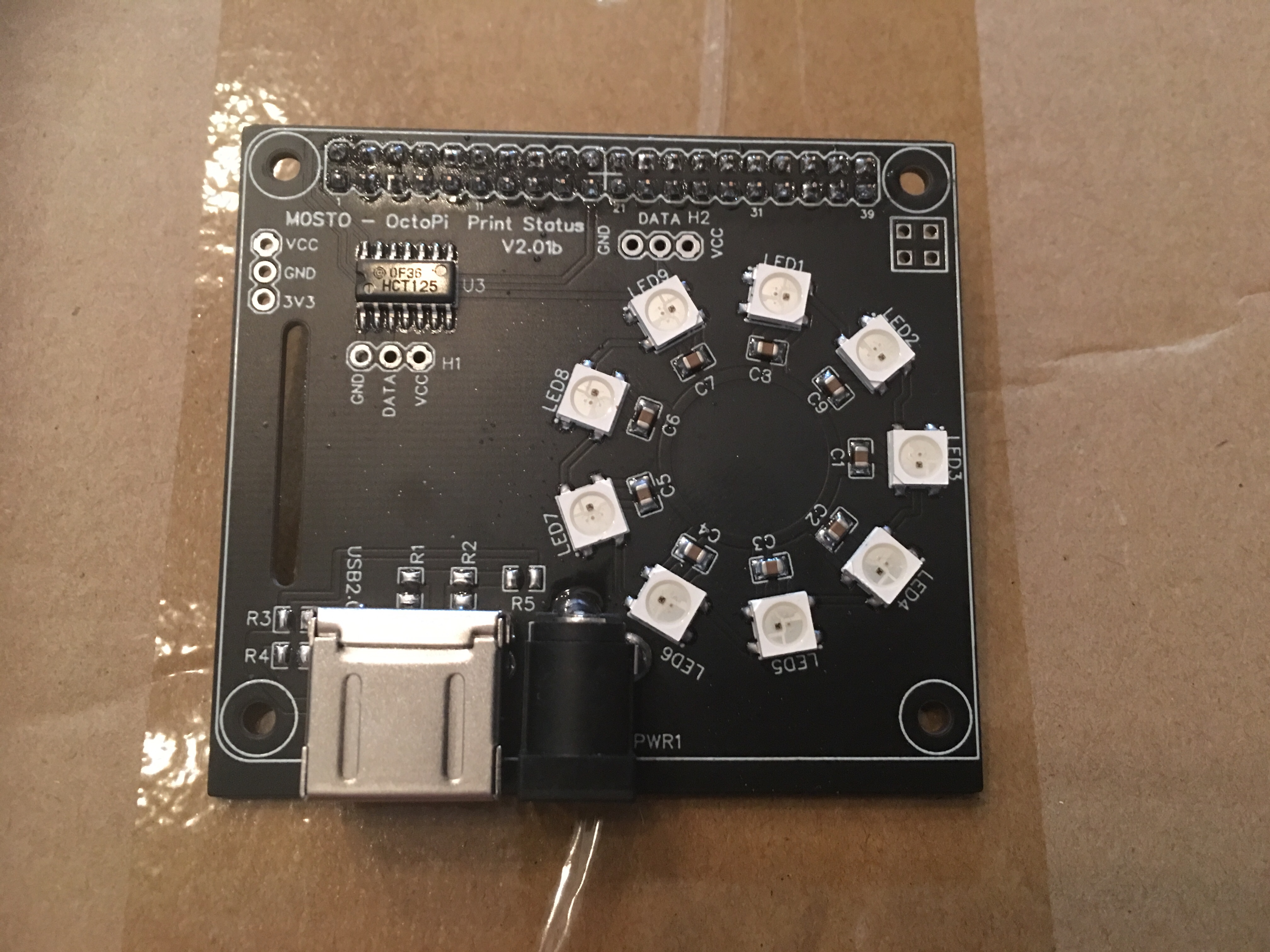
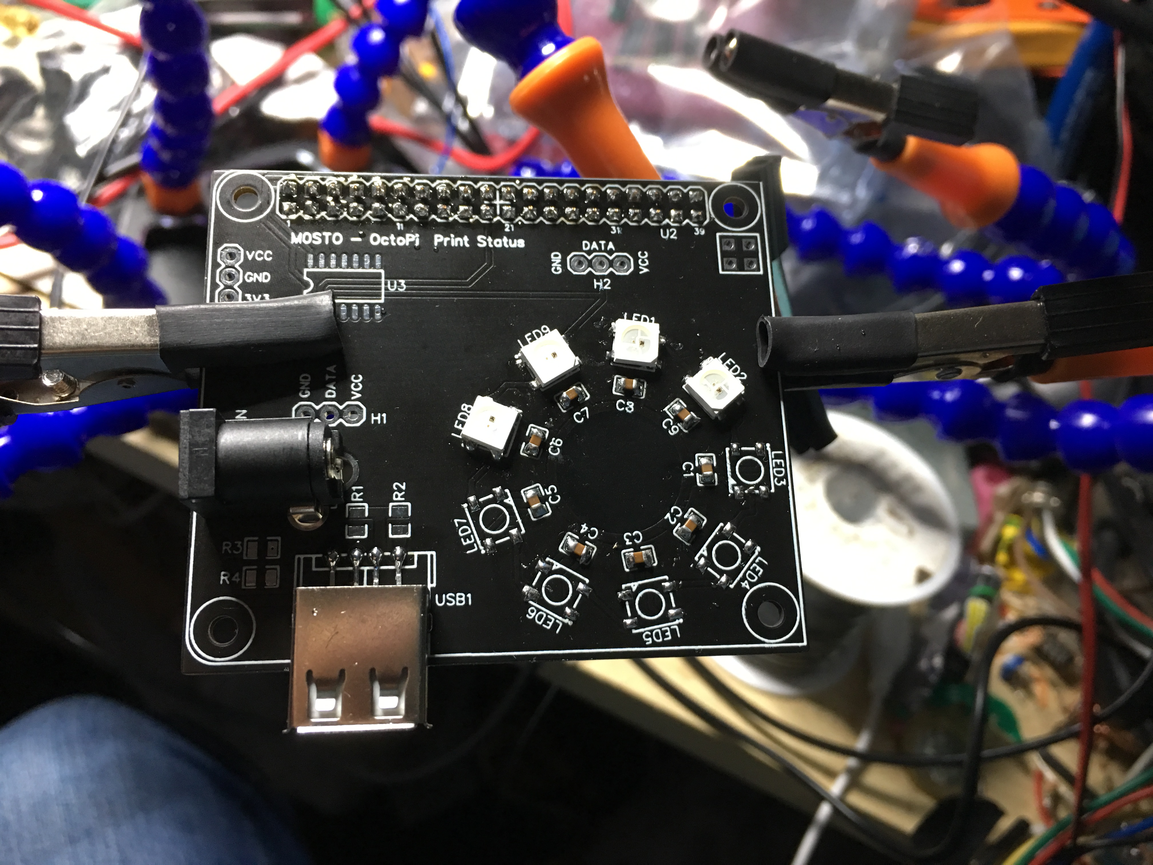
Dear group, this is the probably the last incarnation of the status (unless someone specifically ask me to do something). I will send the Gerber files to Charlie and he can decide when to release them. I do have one more mod that includes a reverse protection diode and a resettable PTC or positive temperature coefficient fuse rated at 3a hold current and 5a trip current which is loads of room for some of the more demanding strips. Anywho enjoy...!
1 Like
Looking good! I like the look of a black PCB. Probably makes the contrast with the lights stronger.
Feel free to release the files yourself somewhere - then you can have full ownership to explain and update with whatever you see fit. I can then provide a link to them from the plugins, or if you don't want to do this, I can probably host them on Github near the plugin itself.
Thanks gents. I'll have to do some reading up on gcode..haven't messed with it much.
Another question for you all, hopefully you can help. I purchased BTF-LIGHTING WS2812B RGB 5050SMD LED lights from Amazon (https://www.amazon.com/gp/product/B01CDTEJBG/ref=ppx_yo_dt_b_asin_title_o06_s00?ie=UTF8&psc=1) I've got a 162 light set running on a 10W power supply. Should be enough to power that amount of LED's.
I get color mismatch on white, about halfway down the strip, it starts going from a bright white, to a yellow white. Front of the strip measures ~5V, end of strip measures ~3V. Why am I witnessing that much drop in the strip? No significant change in color w/ R/G/B tested.
Would a larger 100W power supply help?
FYI - I'm running the LED strip settings at 50% max brightness which seems to help
If you search the internet for 'power injection' you'll find what you need. It's caused by voltage drop, as you noticed, so to eliminate that you can do something like power the strip from both ends. The cabling you use for that will have a lower resistance, so it will not drop the voltage.
You can inject power on any of the contacts along ws281x LEDs, so I think the recommendation is that you inject power every 100 or so.
Thanks Charlie. Sorry about being a bother on this, I'm out of my league, but learning a ton, which is awesome. Looking into power injection, I see no reason that I can not use the same 5V10A power supply to inject power down-stream of the LED strip. 10 Amps should power 162 LEDs on full brightIn fact, I've seen some tutorials that say you can inject at the end of the WS2812 strip with the built in connection and accomplish the same thing (not sure how that works though... to me it seems like they have +5V coming into the same pipe from both directions - which doesn't seem right.
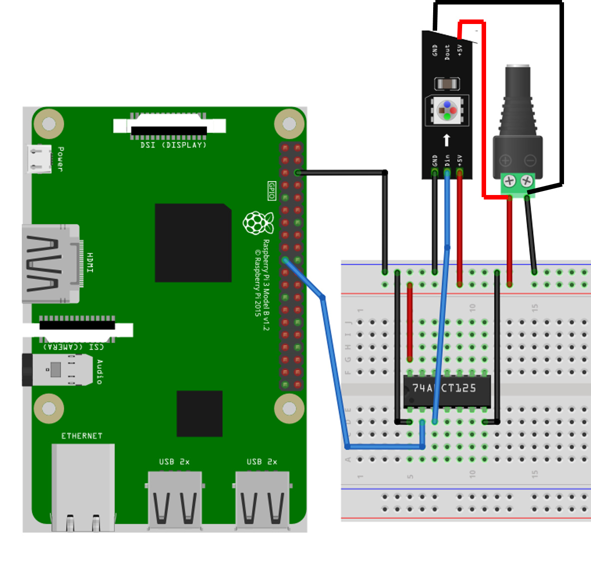
If I can use the same 10A power supply, would this setup work? Or would i have to cut the +5V line somewhere in the middle of the strip, but maintain ground connection throughout, so that I don't have 5V at both ends of the "pipe"
Thanks much for the help!
That should work by the picture, same power supply. No need to cut the 5V, just connect the same supply to both ends. 10 amps is plenty - I have a 10A supply, and have not run into issues beyond voltage drop.
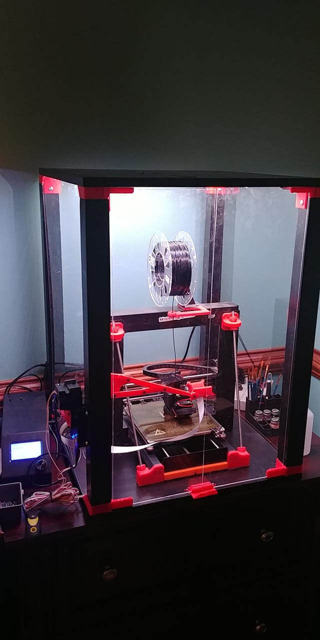
Here's an image of my setup. Thanks Charlie for the help!
Works well so far. I put the @WS_TORCH line in g-code through cura - inserted prior to each layer change. This doesn't work perfeclty for octolapse. Need to figure out how to get octolapse to insert that code prior to picture being taken. More reading to do.
Overall happy with the status color change w/ the LED strips.
1 Like
@FlynHokie Since you are not the first or last person to talk about this, there is now a handy guide over on the wiki:
1 Like
Quick update on this setup above. 2.1mm plug adapter overheated and failed. Not sure why to be honest. Likely something to do with my wire size. Thoughts?
All the connections on the breadboard and to raspberry pi are with standard dupont connector breadboard wires (I belive 22 gauge. The additional wires I have for injecting power to the end of the LED strip are 22AWG also.
Notices after several hours of a print job that the lights were dimming, and the barrel plug adapter was hot to the touch. Shut lights off and unplugged it. Let it cool down, replugged in, and no current flow.
I'm likely drawing no more than 8A for the 162 LED's. Shouldn't all these LED wires be bigger than 22AWG? Or do you think it was a faulty barrel plug adapter that was sent w/ my 5V10A power supply?
1 Like
I have melted Dupont connectors (and the breadboard itself) before, with ~ 120 LEDs. Breadboards are not supposed to be used for carrying mildly powerful current, they are a prototyping tool. The push-fit connections likely create high resistance which can cause things to heat up very quickly.
I always solder LED strips once I have a circuit designed - I recommend you do the same. As for the questions on the wire guage, I can't remember, but the internet will tell you.
Edit: I know the wiring guide is done on a breadboard, but that's the easiest way to explain it. The logic side can still be, but for the number of LEDs you're using solder the power wires, rather than using the breadboard.
1 Like