What is the problem?
I have raspberry pi 3.I want to add a two channel relay module. but I don't know how to connect.How can I do without burning the device?
I'll use octolight and PSU control plugins.
What did you already try to solve it?
I searched the internet, but there are many different comments.
Additional information about your setup
OctoPrint 1.5.3
Python 2.7.16
OctoPi 0.17.0
Ender 3 v2
Raspberry Pi 3b
I assume you have a relay board like this one:
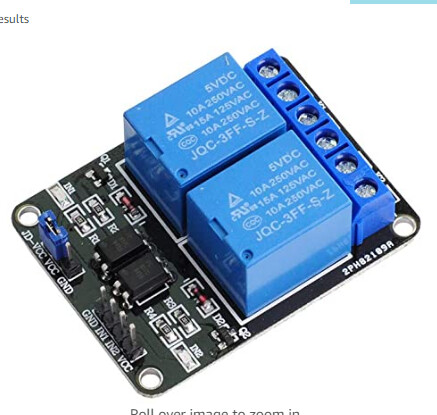
You will connect the GND to any GND pin, the VCC pin to 5v and then the two signal pins (IN1 and IN2) to any of the standard GPIO pins. For relays, your safest ones are going to be anything between 35-39 or 40 (that's board numbering, not BCM numbering. If you're familiar with BCM numbering, you can use 5, 6, 13, 16, 19, 20 or 21). The trick with these boards are, they are usually "on" (meaning the NO connection is connected to the COMMON connection, when the signal to the board is LOW. That means that the PI connects the signal pin to ground. This is usually referred to as "inverted logic" or "active low".
Is there a specific plugin in Octoprint you are trying to use the relay with? It would be easier to help you set that up if I knew what you were trying to do with it.
In general though, as long as you only connect VCC to 5v and GND to GND and NEVER connect IN1 and IN2 to a Voltage line on the Pi or connect one pin on the board to another pin on the board, you'll be fine. HOWEVER, always....and i mean ALWAYS!!!!! turn off your pi and pull the power adapter before plugging or unplugging anything from the GPIO. I have burned up a Pi before because I accidentally grounded out one of the 3.3v pins, so I burned up the 3.3v regulator on the board. 3.3v is what the board runs on. No 3.3v regulator, no RPi magic. So, to be safe, never plug anything into a hot Pi.  (a Pi where the electricity is on)
2 Likes
And take care that the relay board can trigger at 3.3V. Some models trigger at a higher voltage.
2 Likes
That's the beauty (and the reason most of them run) with inverse logic. You're only connecting the input pin to ground to turn the relay on. Since current is flowing to the IN pin from VCC by the relay board, you don't need to pull it "high" to turn it off. You just have to not have it pulled low anymore. So, you can't really fry your pi or the relay board. And that's why they work with 3.3v logic or 5v logic boards.
3 Likes
I'll use octolight and PSU control plugins.
Solved.
GND---GND
VCC---5V
IN1---GPİO36
IN2---GPİO38
Is that true?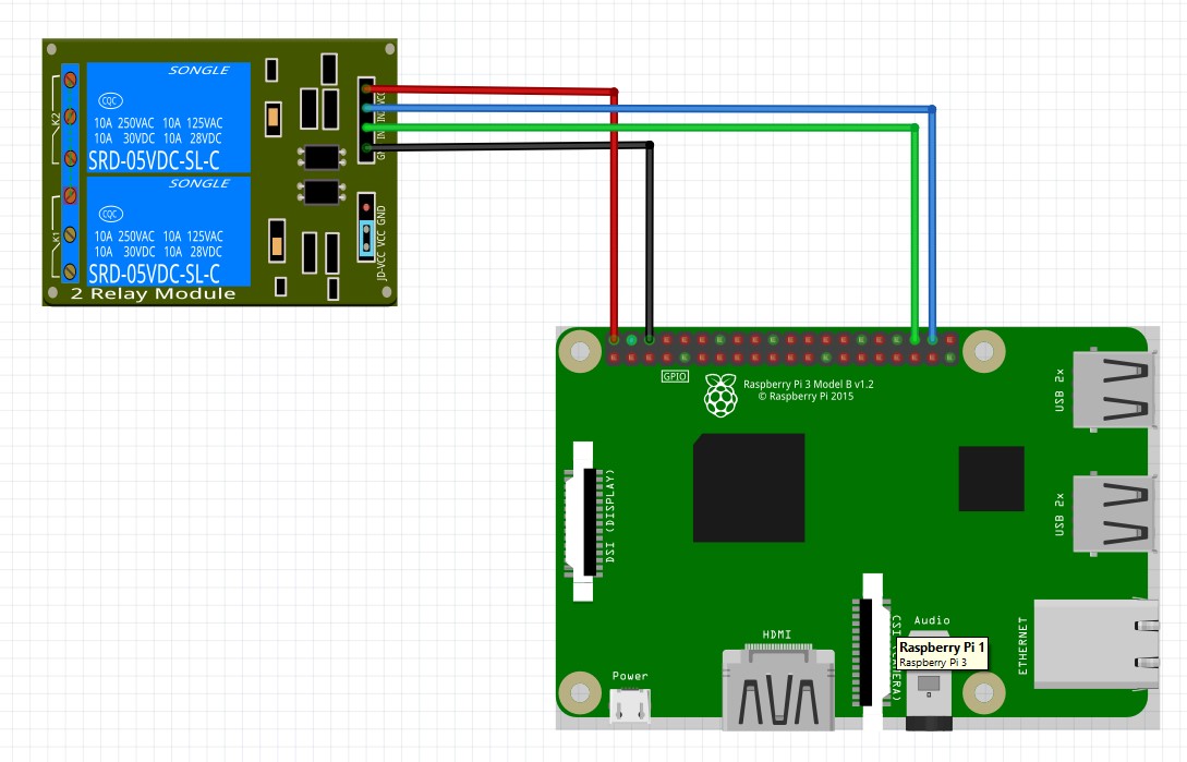
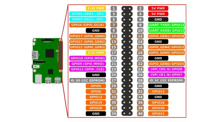
Those are not GPIO35 and 36. Those pins are represented by two numbers, the board numbering, which goes from 1-40, they are pins 36 and 38, and the BCM numbering, which those pins are pins 16 and 20. Here's a pinout of the Raspberry Pi but you can find others by searching for Raspberry Pi Pinout.
I'm confused. You are right. I wrote 36 and 38 while applying.
And everything is working now?
Yes, now PSUControl and octolight are working fine.
1 Like