I picked up a Raspberry Pi 3 B+ to run OctoPrint on my Prusa Mk3s. I'm attempting to hardwire to the Mk3's Rambo board (5v) but I hear the Rambo board may not supply enough power to feed it directly (without using a dedicated separate power supply). The Rambo board can supply enough power for the Pi 0w.
I researched power consumption and it appears the Pi 3B+ uses about double the power of the 3B (690mA vs 350mA). For ease of reference the Pi 0 w uses 230 mA.
My thought process is that if I turn off some of the 3B+'s hardware, such as BT and the new gigabit LAN, it should use less power (closer to 3B or even 0 w power levels ideally per the above link).
I THINK I need to add a few lines of code to the config.txt file to turn off some hardware that's not necessary for OctoPrint. Is that correct? If so, can someone chime in on what lines of code I should add to turn off some of the hardware? I think I can turn off BT and the LAN. Anything else? I just need the wifi on of course to allow OctoPrint to work. I will try to do some before/after power consumption measurements as well (while using an dedicated power supply for now to not damage the Rambo board).
As another way to reduce power, what line of code can i use to underclock the Pi3 B+ in addition to turning off some unused hardware capabilities.
My main goal is to switch off enough unused hardware so that the Pi 3B+ runs at similar power levels as the Pi 0 w (which I started with but I'm abandoning for this project due its inadequacies) and power the 3B+ directly with the Rambo board without an external/dedicated power supply. The main accessory I plan to run off the Pi 3B+ is a web cam along with a few plugins and I MIGHT add a USB light as well, but that's a later phase of this project.
Adding the camera alone is going to put you over on the power consumption I think. It seems to me you would still be better off splitting the power supply input off and add some circuitry (sorry vaguely remember this part but do remember reading about it, just don't have links) to cap the power down to the required 3A 5V power necessary to run the pi. I think it was using a DC-to-DC converter or something like that.
Honestly, I wouldn't risk burning out my Rambo board on all this, to be honest. Give the Raspberry its own dedicated 5V 2.5A (or 3A) power adapter and save yourself the headache.
Want them both to power on together? Use a TP-Link SmartPlug, into this connect an Ikea three-outlet KOPPLA and into this goes your printer and the power adapter for the Raspberry. Add the KASA app to your phone and toggle it from there. Got an Amazon Echo? "Alexa, turn on the 3D printer".
Robo 3D tried to power their Raspberry Pi 3B from their printer board and quietly just disabled the undervoltage reporting rather than to create an actual solution. I remember the collection of trashed microSD cards on someone's desk there which resulted from this; there are consequences.
Caveat:
The Linux drivers for the Broadcom chipset in the area of power management basically suck. The whole let's-go-to-sleep and let's-wake-up-from-sleep areas of state management in the drivers are terrible.
eth0 power:
Attempting to power down the chipset which runs the Ethernet will likely also power down the USB chipset. If you tried to play with this locally, you run the risk of turning off your keyboard/mouse, right? And if you're remoting in via ssh you run the risk of dropping power to the wi-fi adapter as well.
/etc/init.d/networking stop
echo 0x0 > /sys/devices/platform/bcm2708_usb/buspower # Possibly different on the plus
Thanks for the feedback. Sounds like trying to power from the Rambo board is not the best solution.
First world problems... my power strip is full of other clutter where thie 3D printer is stationed. I also like idea of having 1 power cable going to my 3D printer to satisfy my OCD side.
I'll do some research on splitting 24v power from the PSU, reducing it to 5v to power the 3B+.
Your problem is mostly the CPU, the LAN and BT don't do much. The Pi chugs along nicely at 400-800ma, but really yanks down power when the cores spin up to full speed.. which is when you need it. The TLDR at the bottom of Alex's post (raspi.tv) even says so, even if he says otherwise in the main text.
This is sorta why I've done this project:
It's even better with the Prusa because it runs on 24v, making a board like this really efficient.
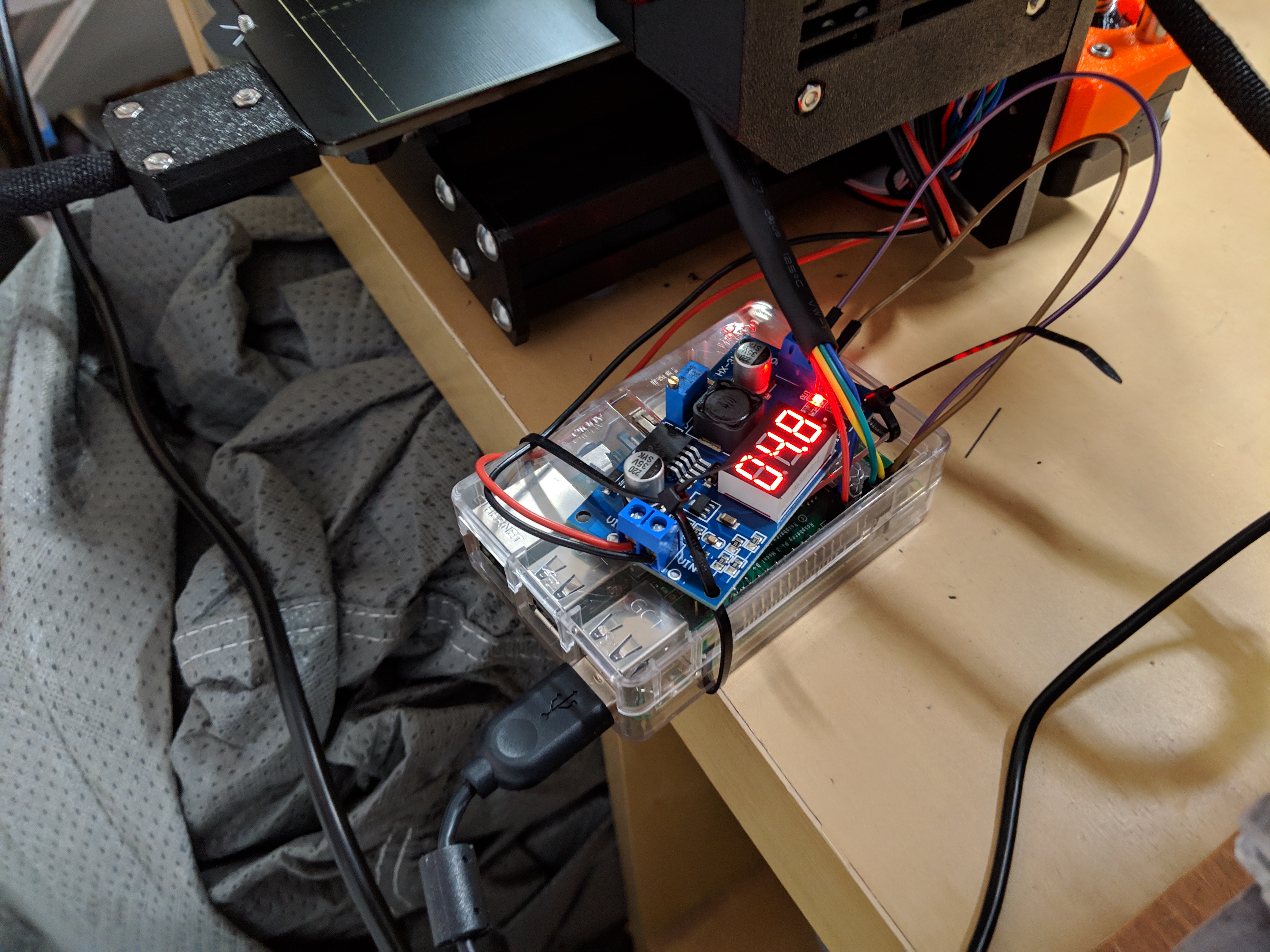
Here's my initial temporary attempt. Not pretty but all wires are hooked up and its working. I'm using a buck converter that has a display on it showing input and output voltage (display reads 0.1-0.2v lower than multimeter). The buck converter was not that difficult to setup, even for someone like me with very little experience in this. I have 18-20 gauge wires running from the 24v terminal of the PSU, connected to the buck converter. Used 4 male to female leads to connect to the Rambo board pins.
I plan to model a case that will squeeze the buck converter (with display showing), RPi3, and 40mm fan into a case, mounted in the same approximate location (bottom rail somehow).
Are there any guides on where to hookup the 40mm 5v fan to the RPi 3b+ and the code needed within Octopi to turn on the fan when the RPi reaches a certain temp? Thanks for all the help so far.
Just quickly chiming in to say: Try shooting for something slightly above 5v as final supply voltage so that you have a bit of a buffer in case of sudden voltage drops. 5.1V is still well within the USB specification (4.75-5.25V) and what is recommended.
Also make sure you do not switch off the PSU without powering down you Pi properly first or you'll risk corrupting your SD. Saying that because for me that toggle switch would be way too attractive.
These are great tips and ones i wouldn't have known! Will bump up to 5.1-5.2v.
The buck converter is a cheap part off Amazon so i think its safe to assume its not that efficient. It does generate some head (~medium let's say) which is why I'm thinking I should have a 40mm fan to cool the RPi 3b+ and the buck converter if both are crammed into the same box.
If anyone has any tips/guidance/resources I can dive into to figure out how to wire the 40mm fan to the RPi 3B+ and have it programmed to turn on when a temperature sensors reads a certain amount, still looking for that info. I suppose the easy route is have it always on and powered by the 5-5.2v output contacts of the buck converter but I'm worried about dust long term which would be another thing to maintain & clean out.
I will share my case that I will model when that's ready for other to use as well.
If this were my project I think I'd go bigger on the gauge of the wires which power all that. Engineers will usually be under the constraints of budget so they'll choose the smallest wire that by spec will do the job. In that case, though, it usually results in a wire that's warm to the touch during operation which means it's dropping voltage in the form of that heat it's creating. It might not be much but I'd rather just use a bigger wire (damn the cost).
I ran some calcs (which I need to triple check) but based on ~3 foot length, 20 gauge copper wire, +5v, the power/ground wires i'm using should allow up to 167 amps (!). This seems very high and much more than the ~2.5 amps the RPI 3B+ should pull at most (plus additional current from 5v 40mm fan and camera but i'm assuming i'm well under 167 amp? For kicks, I calculate 30 gauge wire (3' length, copper wire) comes out to 16 amps. If my math his correct, in theory, i can go even thinner than 30 gauge and still be okay (not that I plan to switch).
Am I doing the math wrong?
I will of course feel the wire for heat as a gut check as well.
Last time I ran those numbers for 2-3ft of wire, an acceptable loss (2-3%) put me at 18ga. That's for the power side, which is 24v. The 5v side should only be a few inches from the buck to the board, which (in the pics) you were running over dupont jumpers.
Ah hah... rookie mistake on my part! i was mixing up the power side (+24v, ~2-3 foot long side) and the +5v side which is currently hooked up with the 4-6" dupont jumpers as you're pointing out.
So if you calculate 18 gauge will do the job, my usual wisdom quirky behavior is to drop that down to 16 gauge.
My rationale is that this will lower the loss slightly, lower the temperature slightly... and over time this will mean that the wires won't deteriorate (usually at the ends). One of the ingredients for making corrosion is heat, btw.
Took my time with the calcs and made some conservative assumptions...
On the 24v side I should need 22-24 gauge wire for it to drop 3% v. I'm running 20 gauge so should be okay on this side.
On the 5v side, at 24 gauge (assumed gauge of current temp jumper wire), I should run less than 7" length (currently 8") at full load. It will likely be 20 gauge wire on this side at ~2-4 inches length when I solder it so should be good here when its made permanent.
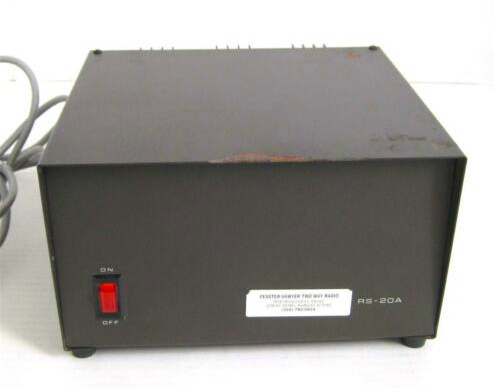
The Pi 3's are Amperage piggies. They really want 3amps @ 5 volts. If you push them, they get unhappy. I'm thinking of taking an ATX power supply, as many YT videos show, splitting off the 12 & 5 volts and putting in testing probe (aka your volt/amp/ohm meter) ports installed. It looks pretty simple, but that RadioShack is gone. Then I've got 300A of 5volts. or so... I have to do my Volt/Ohm/Amp calculations. Those guys that just played in the 1700's
I just received a new Pi 3 B+ to replace a much older Pi B+ and have it hooked up to the 24V supply on my Ender 5 via a cheap DC-DC converter. Works very well except I have to remember to shut-down the Pi before powering off the printer.
I'm just setting up a Pi Zero W as a camera and it will also connected to the DC-DC converter.
Maybe a UPS and automatice shutdown on power loss?
I've been watching youtubes in to learn how to control a 5v fan with th RPi 3 and have it power on/off as a function of temp. I suspect there's got to be a way to hookup a battery pack or possibly even a capacitor to keep the RPi 3 on for a brief period of time if there is power loss.
You'd want to review the specs for it, though. It won't pass all of the "big number" in watts to a single rail (like 5V). In fact, in some cases if you don't load the 12V rail at all and try to load the 5V rail heavily it won't work right.
Just guessing here, but you might see 15A at most on the 5V rail coming out of even the biggest ATX/SFX power supplies. (Years ago, I owned a Radio Shack 20A 5V power supply for my datacenter and it was bigger than an average SFX power supply and certainly heavier.)
Look how beefy this 20A 5V power supply was and this is dedicated to just a single rail: