I am trying to set up a relay to turn my printer on and off remotely via a gpio pin, but I am only able to get about 1.2 volts out of the pin, which is not enough to trigger the relay. I have tried putting the jumper wire on just a 3.3 volt pin, and it will activate the relay whenever the pi is on, so I know that the relay is in working condition. Basically, I am wondering how to get the gpio pin to give a higher output. thank you for any help.
What did you already try to solve it?
WRITE HERE
Have you tried running in safe mode?
WRITE HERE
Did running in safe mode solve the problem?
WRITE HERE
Systeminfo Bundle
You can download this in OctoPrint's System Information dialog ... no bundle, no support!)
WRITE HERE
Additional information about your setup
OctoPrint version, OctoPi version, printer, firmware, browser, operating system, ... as much data as possible
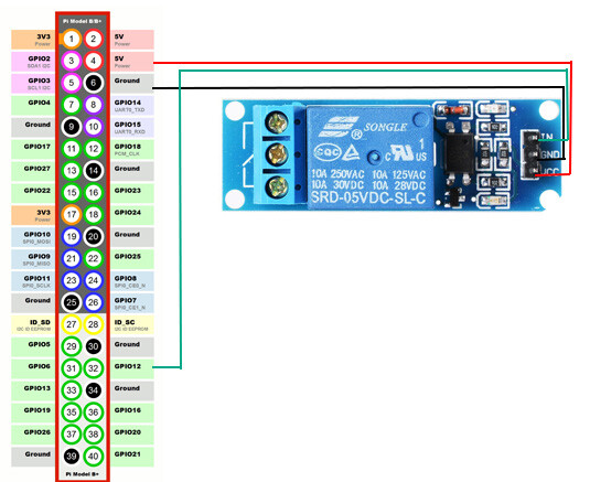
According to this it requires a nominal current of 120 mA. That is much more than what you can safely draw from a GPIO pin (max seems to be about 15 mA). Even the 3.3V pin on a Raspberry Pi can only provide around 50 mA. So to get this relay to work with a raspberry pi, you would need eg another 3.3 V source and a MOSFET.
Following the link jneilliii posted I'd like to ask again: has the GPIO pin been set to output?
If you connect a LED (instead of the relais), does the switching appear to work reliably?
One thing you can do in case that the logic works but you seem to need more power or higher voltage than the raspi's pins can provide is to use a mosfet transistor inbetween which lets a small input signal control a more heavy output side.
Just don't try to pull more out of the GPIO pins than the board can give, this is a way to toast a raspi.
Okay, I used your diagram, and I think that I had the "in" and "vcc" switched around. After switching them around the relay worked fine. However, I was wondering if the relay is still pulling to many mA, and if so, how could I tell.
It's common to mix-up connectors, specially if there are more than 3...
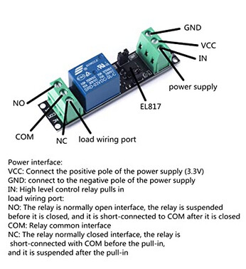
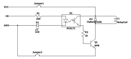
On your Amazon-link there is a comment from a user with the schematic of the relay-board:
there you can see that this is not only a "naked" Relay but a whole steering-board included with electronics like resistors, 1 transistor (!), diodes and a signal-led. The goal is to avoid the case of overload a microcontroller's Outputs, which generally can output only a maximum of about 30mA, so you must provide an external current of min. 120mA, better 200mA (her with +3,3V) to this relay's coil. This current is connected there through a jumper (which has to be closed!). Another consideration is, that coils gives a voltage spike-back when connected to a DC-current, which can damage a directly connected µC's output (this fly-back-current is redirected here through a diode to the mains-voltage). So it's common to separate (isolate) a relay with an optocoupler, here the "PC817", so that the Relay-Input only consumes a small power of the steering-LED (about 3mA) and the external (3V/200mA)-Power does not come from a mostly small µC's regulator...
The everywhere used Songle-Relais (not capable of drivig 30A - I recommend a max. of 10A for it !) is the same as the posted "Gestep" one (=only another brand...), the electrical difference there is, that the latter doesn't provide an optocoupler to protect a µC's-output from overvoltages, etc. It is connected only through a simple transistor instead the optocoupler-transistor, which normally also does the work - if the external provided voltage is smooth enough and not as "dirty" as f.ex. in cars 12V"DC"-electric (mostly with alot of spikes and over-/under-voltages, etc.)
You should only use logic level relays directly attached to Pi GPIO ports - that is as per @jneilliii 's post above, 3.3V. If you need to drive something that is 5V logic, you need a level convertor in line with the GPIO output and the switching device. There are Mosfets and Solid state relays that are logic level switching. From recollection the most you should pull off a GPIO pin is 50mA - but there is a maximum aggregate current limit across all the GPIO outputs which is on the RPi specifications.
Here's a bash script that configures the pin and switches it on..
This runs on an instance of Octoprint on a Pi attached to an Anet A8. It works :-).
The output device is a logic level relay.
This one turns the 240V supply on via a logic level SSR.
#!/bin/bash
# ****** inputs *****
# GPIO17 filament runout
# GPIO18 spare
#
# ****** outputs *****
#
# GPIO27 - power relay
# GPIO22 - 5V lights control relay
# GPIO23 - 12V FAN control relay
#	controlboard fan, Hotend fan
# GPIO24 - spare
#
# power relay to printer PSU controlled by GPIO
mydate=$(date)
echo "Power up printer engage mains relay"
echo "Power up at " $mydate >>~/guicontrollog.txt
gpio export 27 out
gpio -g write 27 0
/usr/local/bin/lights_on.sh
echo "System switched on at " $mydate >>~/guicontrollog.txt
it also switches the lights on BTW.
If your kit is precious, its always better to use optoisolated relays / SSR's because there's no chance of a fault on the power control side blowing up the Pi. This is standard practice in Industrial Control and hazardous environments I used opto-isolation for sensors in paint shop control and monitoring systems. Should the Anet be recommissioned I will be changing the power control system.
I should have added, its also bad practice to directly power a fan off the GPIO 5V rail, DC motors generate a 'back EMF' - a reverse voltage spike every revolution, if these are big enough they can blow the Pi power controllers. If you must run a fan off the +5V, run it via a transistor which will limit the current running through the rail AND isolate the back EMF spikes.
that's good to know. I have 2 Pis that I've been running Noctua 5V fans on for a long time direct from the 5V rail. Any recommended transistor/size, ideally that can be added directly to the wire.
This is one method I bookmarked a while ago, what I REALLY like is that this method offloads the monitoring task to the Raspberry Pi processor chip. Neat. Diagram shows an S8050 npn transistor ground switching the negative wire to the fan. I should have added that its not a good idea to run the fan +V feed from a GPIO pin, but ground switching is OK as the fan +5 is connected back into the Pi 5V input, whereas the 3V3 and GPIO signals are derived from the Pi's onboard power regulator.