I'm quite new to 3D printing and to this community, therefore a very brief introduction of myself:
I'm living in the south west of Germany, >40 years old and I'm an electronics engineer for high reliable analogue hardware.
I have some experience with my DIY CNC router and therefore some questions to the mechanical adjustment of my 3D printer, which is IMHO the basis for good prints...
I made a new FW version for my printer (Anycubic i3 Mega with Ultrabase) which enables the Mesh Bed Leveling (MBL).
With the OctoPrint terminal I was able to send and receive all the informations regarding the MBL - it works.
But the finest Z steps in the Ancubic printer and in the OctoPrint control panel are 0,1 mm. While performing MBL I feel, that these Z steps are too coarse and for best results they shall go down to 0,025 mm.
There are no chance to change this in the Anycubic printer...
Therefore my question:
Is it possibe to have more fine steps (e. g. 0,025 mm) in the OctoPrint control panel?
I'm looking forward to your answers!
Have fun!
LG kaskade911
This is mostly a firmware and mechanics question. Depending on the printer design and the smallest value the firmware will recognize, you should be able to use GCode in the terminal to move to an arbitrary height. Anything you can do in GCode you can create a button for in OctoPrint. Most printers aren't designed to be stable for Z steps under .1 or .05, but this depends on step degrees, Z screw type, Z screw resolution, Z axis backlash, etc.
Hi supertaz,
THX for the quick reply.
With an appropriate GCode (G1 Z1.025) I can control my printer down to 0,025 mm. Even the TFT shows this value (I assume I can go down to lower values....).
But working with the terminal and type in all this values during adjustment (for 25 MBL points) you will become crazy....
Is there a tutorial how to make this button (incremental Z values of e.g. +- 0.025 mm)?
I was not aware of this opportunity...
perfect! Many THX!
It works great. I installed the Custom Control Editor and after a few minutes I had my own buttons.
With this, the manual bed leveling procedure is a not a big deal. I do not longer think about installing a BLTouch or something else.
The best preparation for an easy and reliable MBL are IMHO some minor mechanical upgrades:
Only three (!) bed level screws - Each of them are adjustable without affecting the adjustment of the others. The bed is not bended by the fourth screw...
Get rid of the springs under the bed and substitude them by self locking nuts - you have to adjust the nuts only one time. You can remove and install the bed without a longish readjustment of the spring loaded screws.
Hi Kaskade,
could you walk me through the process of creating those buttons cause I'd like to do same thing to manually adjust my UBL. I have the same printer than you but disconnected the LCD screen... It would be helpful to me to have manual adjustment when I setup my mesh. Thanks a lot
Adjust and level the printer mechanically as good as possible. See as well my recommendations for a minor mechanical update of the printer. It makes life more easy...
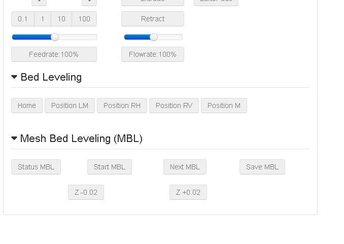
Install/activate the "Custom Control Editor" as a new PlugIn into your OctoPrint using the "Pluginmanager" in "OctoPrint Settings" and open it.
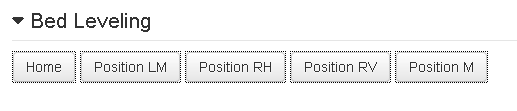
Right click in the green frame and do "create container" - this is the name for new area (eg. "Bed Leveling") where you put in the new buttons.
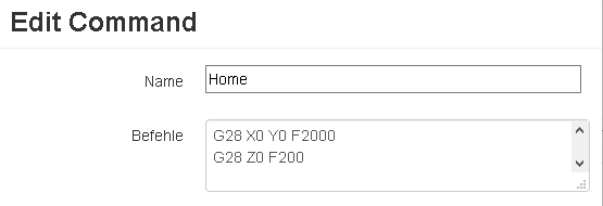
Right click on "Bed Leveling" and create a new command - this is the new button (eg. "Home"). With a right click on the button you can re-edit the G-Commands working in this button (refer for G-Codes as well to the Marlin documentation...)
My "Home" button:
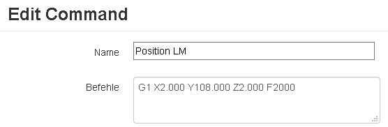
My "Position LM" button:
Continue in this way for the others...
Here are the G-Codes for my MBL procedure buttons (please refer to the Marlin docs....)
Status MBL
G29 S0
Start MBL
G29 S1
Next MBL
G29 S2
Save MBL
M500
Z -0.02
G91
G1 Z-0.02
G90
Z +0.02
G91
G1 Z+0.02
G90
The values for each MBL point are visible after the "MBL Status" command in the "Terminal" view
With drag&drop your can arrange the buttons as you want.
For a better visability you can play around with "Width" and "Offset" values
thank you for your advice, I have just starting using my own customized Marlin FW with MMBL enabled on the same printer, and what can I say, finally I don't need to worry about it anymore. I coincidentally already had installed self-locking nuts instead of springs before (https://www.thingiverse.com/make:564220), but I did not think about doing only 3 screws.
Two questions on your upgrades:
Did you just remove both the self-locking nut and the screw underneath or just the nut?
Did you choose a specific corner (the one most bent downwards/upwards) or just any of the three?
I removed the spring only and stick of course to the counter screw on the bottom.
I choose no specific corner. The underneath mechanic is not able to bend the UltraBase...
So I choose the mid point of the left both screws, drilled a further hole and assembled a 5th screw, which is the 3rd and last to adjust the stuff mechanically (but finally you could take both outer screws and adjust them synchronously- this should have the same effect)
The picture shows the three screws, but only the middle one is used for adjustment. The outer ones are not fixed.
This picture shows the self locking nut and the counter screw.
The cardboard underneath is for insulation purposes
Sadly the images seem to have failed to upload, I can't see them. But I can imagine how it would look. Right now I have adjusted one corner to have only a nut underneath to secure it but nothing to lock or bend in between. Works quite well. Together with MMBL I finally have great adhesion over the whole board. I won't drill a hole for now since it works great but if I ever run into issues, I'll come back to you.
Hey! Hope you can see this, wanted to say massive thanks for posting this, really helpful! I was wondering if you'd know how we'd set the Z offset with this method? My LCD is busted and it'd take a while to arrive
 Many THX!