Nice project! Will you put boards up for sale on Tindie or similar?
How about a battery pack connector for a LiPo or similar and some charge control? A mini UPS? My biggest gripe with the Pi's is that a sudden power loss can wreck havoc on the file system making it unbootable.
And a button for safe power off (that will be automatically triggered if the power is out and the battery is getting low) Also, if there's an RGB LED strip connected, do short flashes of red to alert the user!
For now I'm not using an RPi for octoprint, but an Up Squared that is way too powerful for the job. I'd like to use the Up for other, more demanding tasks
I'll put 'em on Tindie if they are popular, but they aren't cheap, either. That's part of why the Pi doesn't have this built-in.
UPS prob needs to be external to this project, there are 18650-style PiUPSes out there.
I had three buttons .. and a few neopixel-style LEDs .. and a 16-LED bar graph in various versions. Just too many things to go wrong. I will probably add the buttons back- it takes three to properly handle "shut down Pi", "start up Pi" and "cancel print". On the bright side it's easy to add those on without this board.
It's plain Ubuntu 18.04 LTS. When I installed it was just for testing, to see how octoprint performed on that hardware. So it's not running the custom Linux kernels that would give me access to all the cool hardware features on that board.
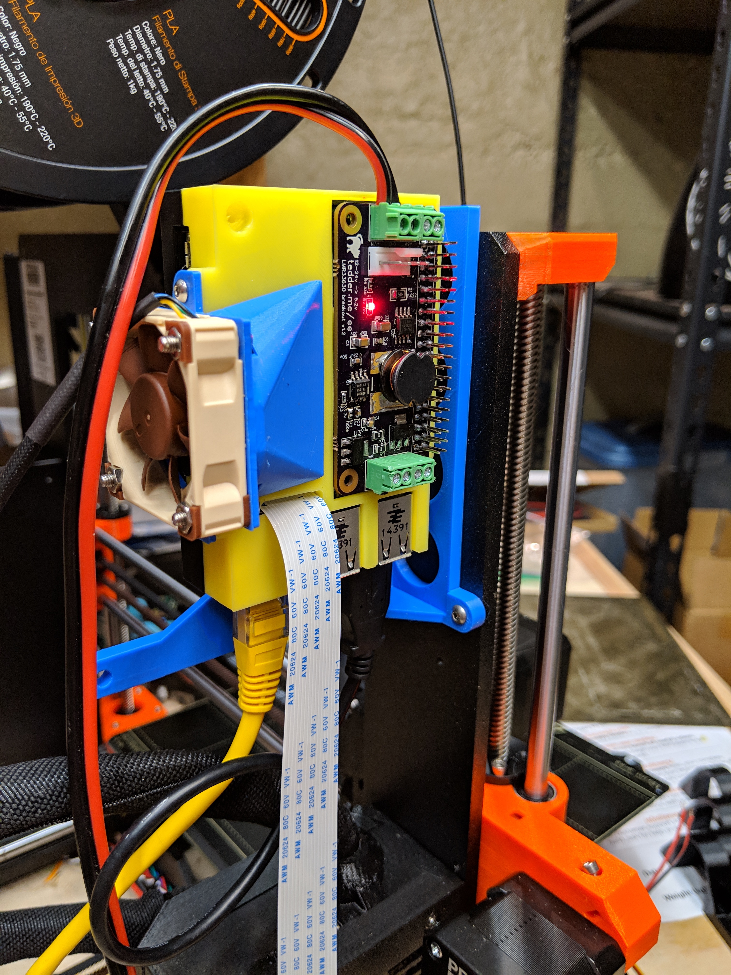
Next iteration in this pic, though I have a test board enroute and will have another iteration coming after that before it is even possibly ready- the fan pins and level converters were wrong and the MOSFETs were wrong. doh. So I'm doing a "test board" with a few designs on it.
But anyhow, you can see the shield mounted, the fan mounted, and the whole thing on a bracket that sits on the back of a Prusa.
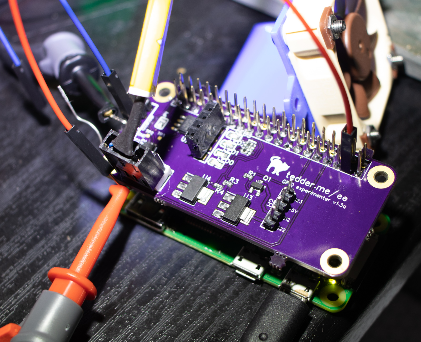
I've been using the previous version on one of my printers for a few weeks, and a waaay earlier version in my off-the-grid shed, which has a Pi connected to its solar panel. But thye are just power shields, with the one on the printer having voltage/current measurement. My experimenter board was helpful for me to explore a few things:
I got the MOSFETs sorted out. They'll be really nice for LED control.
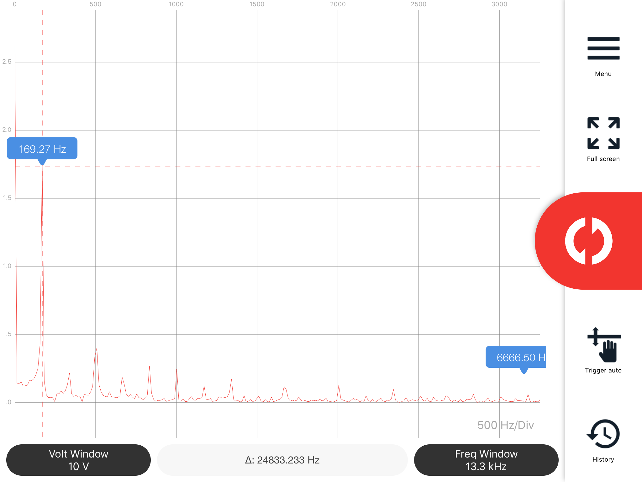
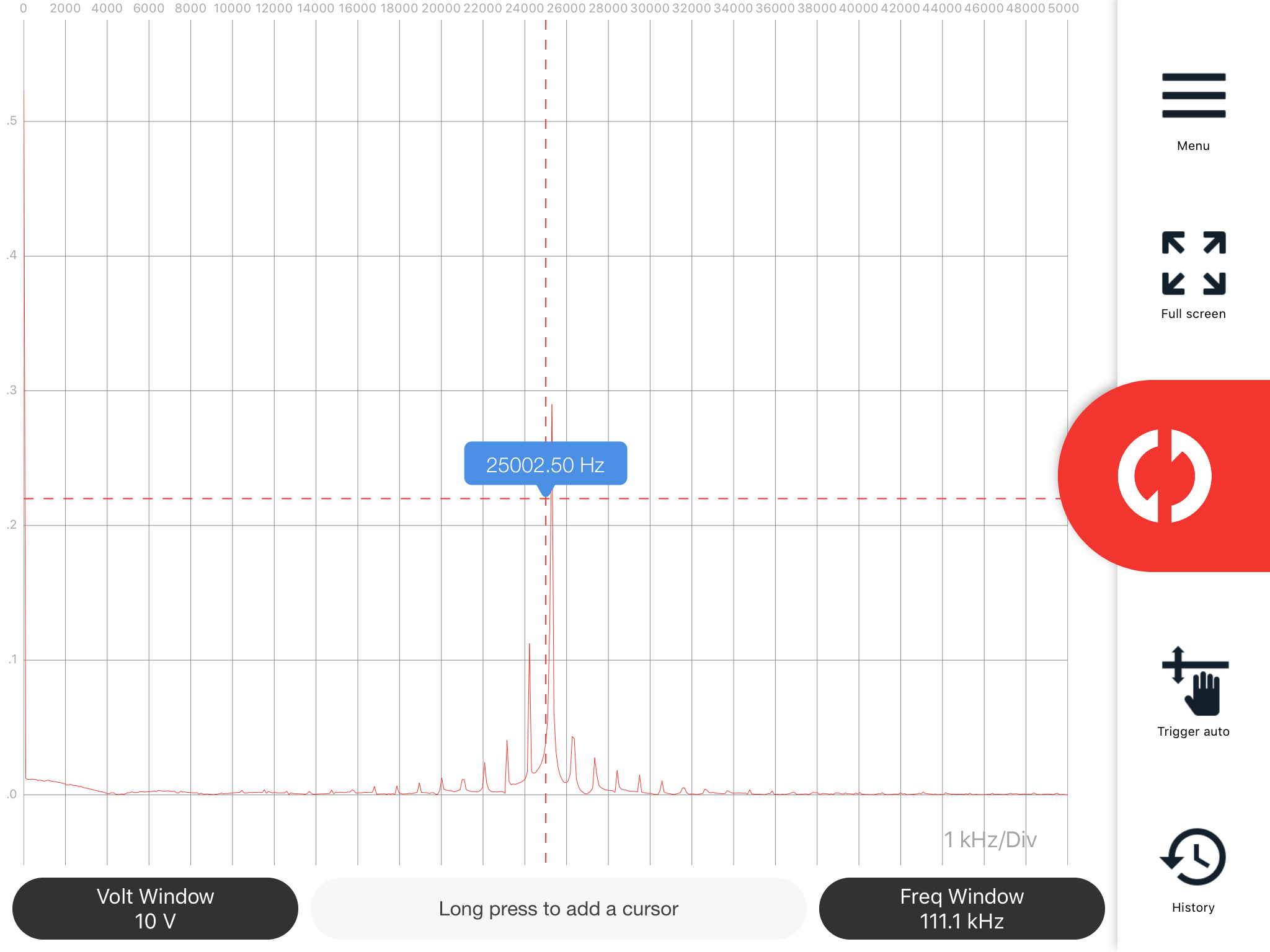
I got the 4-pin fan figured out in many ways: I can control it and safely sense the rpm using the 3.3v GPIO, it is 5v powered, and I've verified that I can push a pwm signal with a 25khz "carrier" from the GPIO and can read the fan speed pulses in Python. (see oscilloscope screenshots below)
I'd experimented with a 4-channel LED controller and can turn them on/off/dim/blink but .. is it worth anything? I don't think so. Initially I thought I'd use it to do some level shifting for the fan.
screw terminals are kinda iffy, and I don't really like many other board connectors. Maybe I should just use screw terminals for the power and use dupont headers for the rest? They are easy to plug/unplug, at least. Or a DC barrel jack for power?
sale plan:
finish up some proof-of-concept standalone scripts
create a rudimentary octoprint plugin (display power+rpm, set fan speed)
I'll publish the plans and the BOM along with the pricing I pay to get a couple of them done.
Sell a 'base model' with all the SMD soldering done (~$20?)
I kind of like the green variety of DC screw terminals, to be honest. They just need to accept the gauge of wire that's appropriate for the circuitry on the high side.
Phoenix makes a type of plug/connector in this space. It's not really connector-compatible with a lot of the boards we use... or is it?
I wouldn't trust a Dupont connector for the power you might see.
I think the green ones in the back would be the ones that are the most useful to someone like me.
At least one of the OSEPP motor shields has connectors which are compatible with that. Unfortunately, they don't appear to sell the stand-alone plug; it just comes in their robotic kits in number. I dunno, maybe this is a Phoenix-style plug we're talking about. Whatever they are, I do love them.
Also, I tend to use this guy when someone presents me with the standard DC barrel connector jack. I can't say that I love this arrangement, though. To me, it presents an amazing leverage point where that soldered-down connector can be destroyed from its soldering to the board.
To anyone adding a DC barrel jack to a board: why not move that barrel connector to the center of the board and free up some space where the plug/cable can live and further, include two rectangular cutouts so that we might then zip-tie the cable to the board (preventing accidents)?
Definitely not talking about using Dupont for incoming power- even though Ohms Law is forgiving with a voltage being 2x-5x higher, just.. no. Though for the others it is cheap and space efficient.
Thanks for the part. I'm mobile but I've looked for hours on BOMs for this.
That's a 5.08 spacing, so a good example of what I meant by "my way or space for an alternate". The current board uses 2.54 spacing for the screw terminals but that's waaaay too close for any stranded wire.
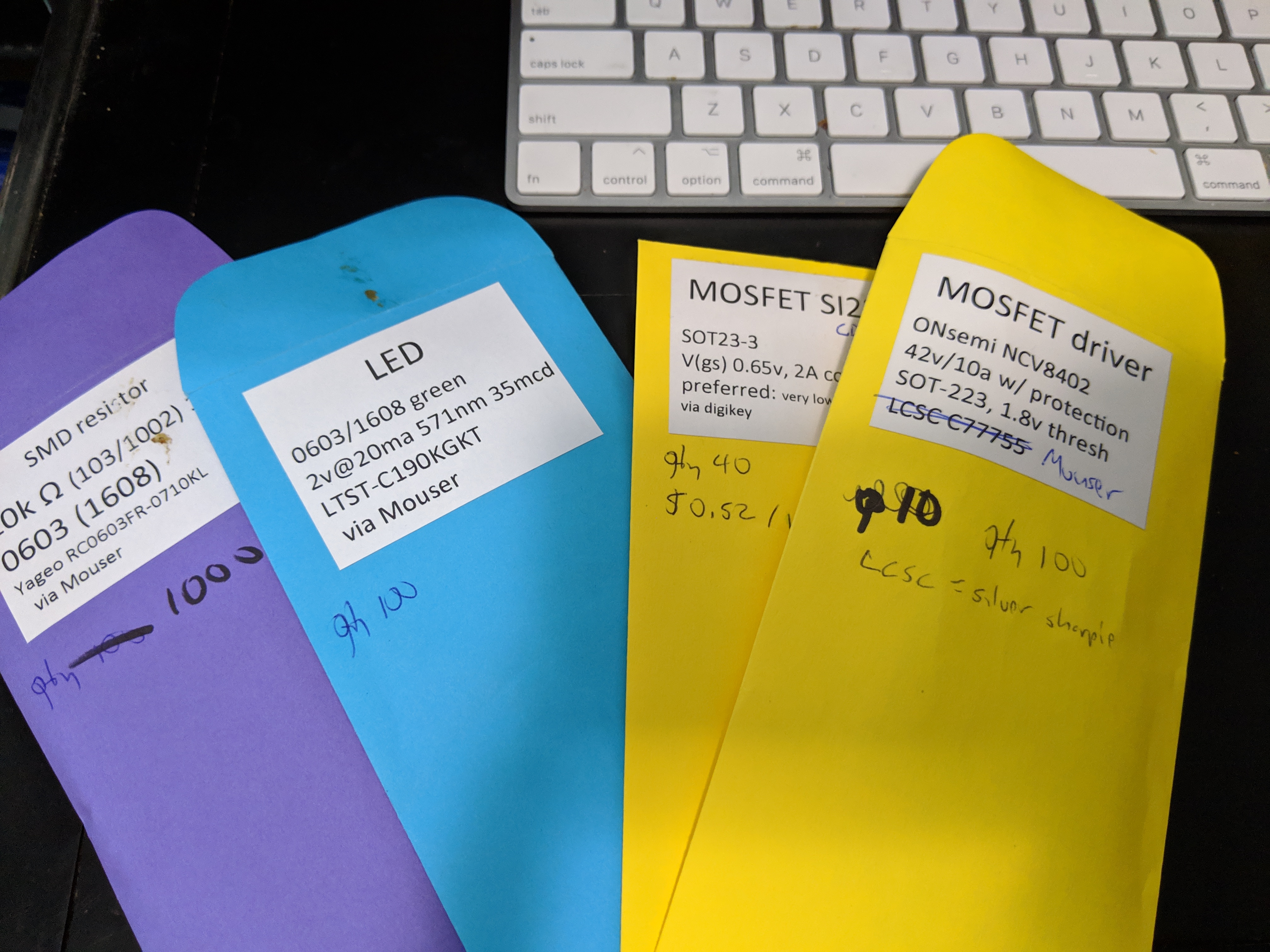
this isn't my first rodeo I prefer Mouser, slightly, but order from both. Here are some of my jellybeans and other parts that were within reach while typing this:
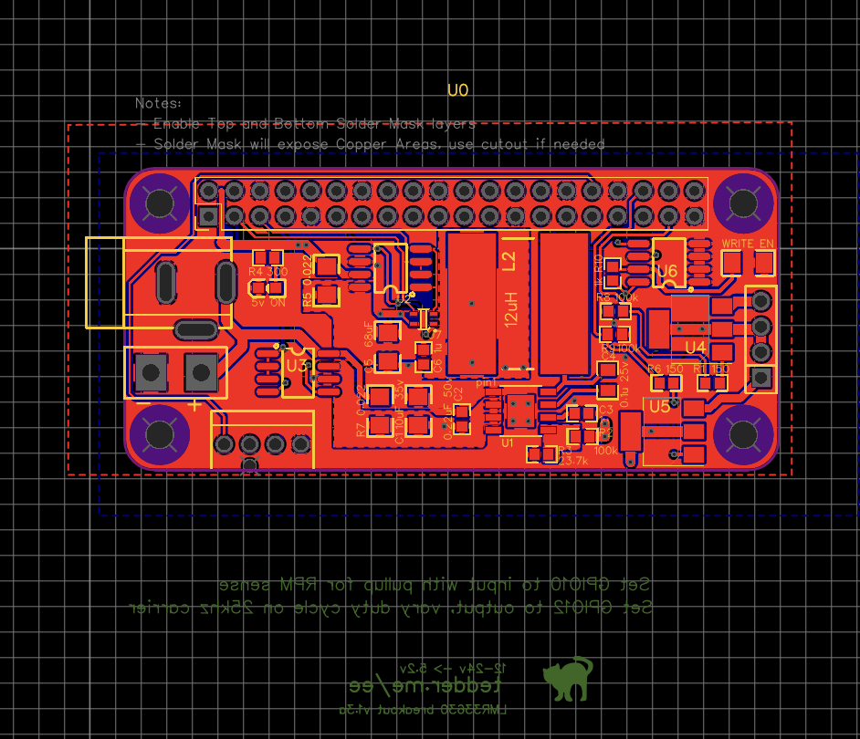
New design is routed, so I've gone slightly crosseyed. Still need to add the text/graphics (at the bottom of the screenshot) and update the BOM (added temp/humidity sensor, second current/voltage sensor on supply side). Those are on the "full" board, the stripped board doesn't change much except I added true HAT compatability with an eeprom.
Created the tindie page with the options, but obviously I have to recalc those from the BOM again.
Are you going to provide little offsets for the person who's using this on a 3B, for example? It looks like two of the holes line up. I'm thinking maybe something for one of the other two holes which helps to provide stability. The little bump under the PiFace Digital 2 comes to mind.


