Hello everybody.
Could not figure out why my Relay in OctoPrint Enclosure plugin does not work...
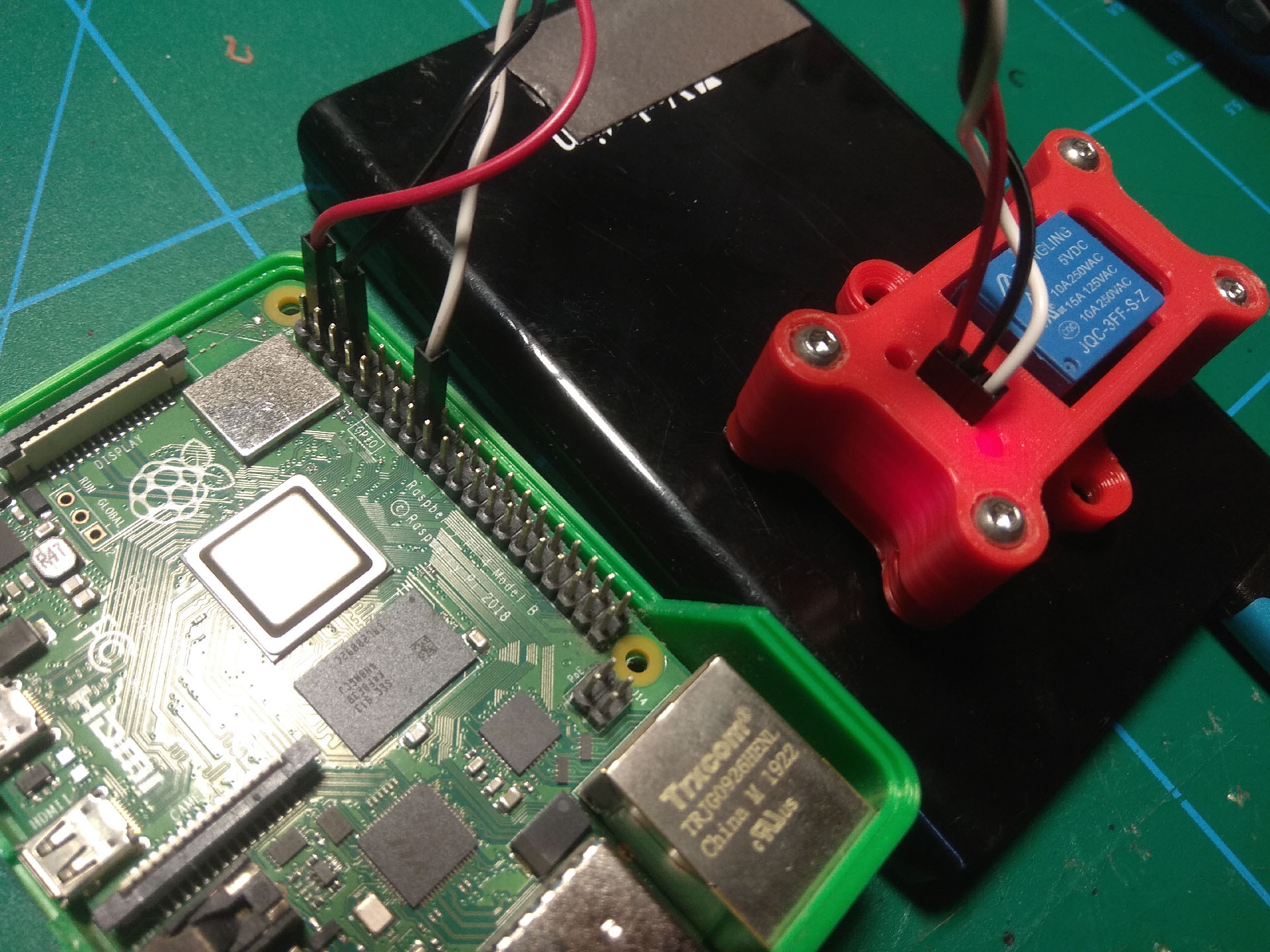
My setup: Relay conected to 5V, GND and GPIO23
Output Type: Regular IO; IO Number: 23; (other boxes unchecked)
Advanced options: checked only "Use SUDO"
I'd like to do something similar but am stuck on wiring relay module. I have read that JD-VCC is used to supply power to the relays. Do you literally remove the jumper and run 5v to the JD-VCC pin?
Hi I want to control light and power with a double relay the ones I have, have JD_VCC function. I have put them on test and found the io signal pins would have to supply a ground not 5v as I was expecting, could you tell me what the io pin you use is doing please?
@Jan_Reich Thanks for getting back to me. I did a google around and it seems is you leave the jumper in place, everything (relays, opto and drive transistors) fom the Vcc pin. Did you put 3.3v or 5v on the Vcc pin?
Agreed but if you use 5v for the logic but Pi uses 3.3v for it's logic, isn't that risky? Also aren't you risking pulling the 3.3v rail down or putting noise on it? From the video Quad.... posted it looks like
Since you are only sending a 3.3V signal FROM the grip pin to activate the relay it is no problem. Also, many of those relay modules are optically isolated, so extra safety factor there.
My understanding is that you want activate the relay by pulling the GPIO pin to ground. It will float at 3.3v which is high enough to be "high" for 5V logic.
Thanks all, time I actually fired up the relay modules I have and actually see whats happening. Still unclear re. how much current I can draw before 3.3V line gets sucked down or even worse kills the onboard regulator.
 Thank you for noticing me!
