Looking for help on how I can use an LCD with PSU control.
The only thing I can think of is soldering a lead onto the bottom of GPIO 2 and 3 so I can split the 5V and pin 3.
Wondering how other people are doing it.
Looking for help on how I can use an LCD with PSU control.
The only thing I can think of is soldering a lead onto the bottom of GPIO 2 and 3 so I can split the 5V and pin 3.
Wondering how other people are doing it.
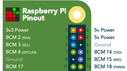
One of us is confused. BOARD pin 2 is 5V (as is BOARD pin 4) and BOARD pin 3 is half of the I2C interface. Neither of these is a ground pin.
Or did you mean BCM 2 & 3 (I2C interface)? If so, you need an I2C multiplexer to use multiple I2C devices on the same pair of pins.
You didn't indicate which display you're trying to use. You didn't indicate how it's connected. We might infer that it uses some size of GPIO header (unknown) but you didn't say this. You didn't say which model of Pi you have.
Pi 3B
GPIO 3.5" LCD
I can use the GND from pin 34 or 39.
PSU Control needs 5V from pins 2 or 4 and data is pin 3 which the LCD doesn't use but the header is taken up by the socket.
Actual screen: https://www.elecrow.com/wiki/index.php?title=3.5_Inch_480x320_TFT_Display_with_Touch_Screen_for_Raspberry_Pi
The documentation indicates that there are no connections for pins 3, 5, etc. They list 26 pins so maybe this isn't a full 40-pin header. Perhaps it's 13 x 2...? This would explain why pins 25 & 26 are the highest two. So then in theory that leaves BOARD pins 27-40 alone.
Looking at the PSUControl plugin's screenshot, can't you change the Sense GPIO pin to BOARD pin 37?
I'll try that.
But where do I get the 5V from?
If you're into soldering, you could solder a male or female GPIO pin:
PP1 5V from micro-USB
PP2 5V from micro-USB
PP3 GND
PP4 GND
PP5 GND
PP6 GND
PP7 5V after polyfuse
Flip the Pi 3B over and look for these near the microUSB where you'd normally power it.
Another way might be to mod your LCD/TFT header board to remove the two end pins for both 3.3V and 5V. You might use a Dremel tool to just simply cut it out of the picture. The 3.3V is doubled over on BOARD pin 17 and the 5V is doubled over on BOARD pin 4 anyway. It's pretty destructive and kills the warranty on device. But soldering the 5V on the Pi would do the same so it's "six of one and half a dozen of the other".
If you're familiar with wire-wrapping techniques from the old days of phone closets, you might be able to use solid wire to wrap one of the 5V pins before adding the header on top of that.
Looks like wrapping is the cleanest option. Ordered the tool. Who knows how long before I get it.
Thanks for the ideas.