They just don't turn on. The spec sheet says they require a 5v for the data line. Coming from Arduino I din't even think about the PI having 3.3v GPIO pins.
The PI's ground and the LED's have a common ground.
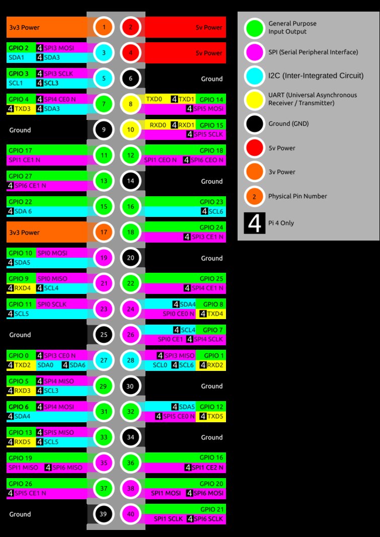
Thanks for clearing up the pin number! The numbering on the PI is a little nuts for someone new.
Interesting. Technically the strips do require 5v logic, but usually the 3.3v from the pi works. I’ve never had to add a level shifter, but some people have.
"Note that you might be able to get your NeoPixels to work without any level conversion, but it's not really guaranteed because the data line needs to be at least 0.7 * VDD (5 volts), or about 3.5 volts. Try one of the level conversion options below if you can't directly drive the pixels from your Raspberry Pi."
So if your Raspberry Pi has peripherals and is loaded down, the internally-available 5V may be slightly less. So if you ever see an undervoltage condition then give up trying to do NeoPixels without a level converter in place. I personally tried the diode-only version and I did not have success with that. And I used a 10A 5V switching power supply for the 60 LED ring and still this was problematic. I have purchased several of the logic level converters but I haven't returned to this project in a while.
Interesting that your experience has been so different from my own. I’ve not used the Adafruit branded strips though so maybe there’s a difference there.
I connected the osmelly scope to https://pinout.xyz/pinout/pin19_gpio10. It had a signal that looked like data of some sort. Then I connected the transistor to boost the signal to 5vdc. Next I connected the LED strip's power cable. Flipped the switch and nothing happened. Checking things over I realized my mistake.... I had left the bench supply at 12vdc! The strip is toast... I think. I don't have anything to test them out at the moment. I might grab an arduino just to make sure. Thanks for the help! I think it will work when I get a new set of LEDs.
Hi I have/had the same problem of the led showing white then every now and then running across in a different colour,so I checked the core_freq and it is at 250 but I uncommented the audio, now nothing no lights at all. cannot get this puggin to work
I had the same problem on a raspberry Pi4. I think the plugin RGB status doesn't work on a pi4 using GPIO n10.
I tested the led light on a python script, and it worked on GPIO 18 but not 10.
Then I've installed octoprint on a old Pi2, and everyhting works great...
If we're talking about BOARD pin 10 then it looks like for the Pi4B it could be different things, depending upon which interfaces have been turned on (via sudo raspi-config). When you makes changes, it brings in different kernel overlays during the bootup process.
That said, you can see that it might be a receive line used by the UART if enabled or be a clock pin for SPI if that's enabled. Otherwise, it's available generically. That's why they're called General Purpose—they could be this or that, depending upon the settings.
You should go visit the plugin author's repository, create an Issue and let him/her know about how the Pi4 is now different.
Hi Eric, I am new to this and I have problems with the leds w2812b, I have them connected GPIO 10 = PIN19 but I don't have to put in PIN LED and LED DMA
The strip-of-programmable-LEDs like this are notoriously hungry.
Power them separately from the Pi itself
Share Gnd with the Pi
The Pi pushes 3.3VDC data and these LEDs expect 5VDC logic level.
Read what Adafruit has to say on the subject, especially the second page on that tutorial.
What I've found that works well is to add a PyBoard to your Pi, connecting this via USB. The LED strand then is connected to the PyBoard. Power the LEDs as described above. The PyBoard dishes up the 5VDC logic level that makes the LEDs work as expected and allows a lot more interfacing options.
I've been reading this thread, troubleshooting my RPi 4 setup, but still cannot get this plugin to work. Is there anyone out there who has this plugin working correctly with a Raspberry Pi 4? I have a 16 led NeoPixel ring I'm trying to get working atm.
Yes, I have a 5v 2A power supply for the lights, common ground shared between lights and the RPi. SPI enabled, Pi added to usergroup, but still no luck. The only thing I haven't tried that was suggested from this thread was a logic level shifter. Considering what's going on in the world today, IDK how high on my priority list buying one is right now. But I do have a couple smaller arduino clones (mini or micro) that I may be able to connect to the Pi's GPIO and maybe try that strategy. I also have a RPi 2b that I can try to get working with Octopi/RGB Status Plugin, just to see if there is any difference which generation Pi used makes.
You've managed the first two parts: separate power but shared ground. The next step is as you're now confronting, the logic level is 3.3V versus 5V. It's best to read the Adafruit tutorials on this. Especially read the safety callouts on the Basic Connections page. Note the part about the 470-ohm resistor.
If using a 3.3V microcontroller you must use a logic level shifter such as a 74AHCT125 or 74HCT245.
Pretty sure I've also gotten this to work using any of the Arduino boards to drive it directly.
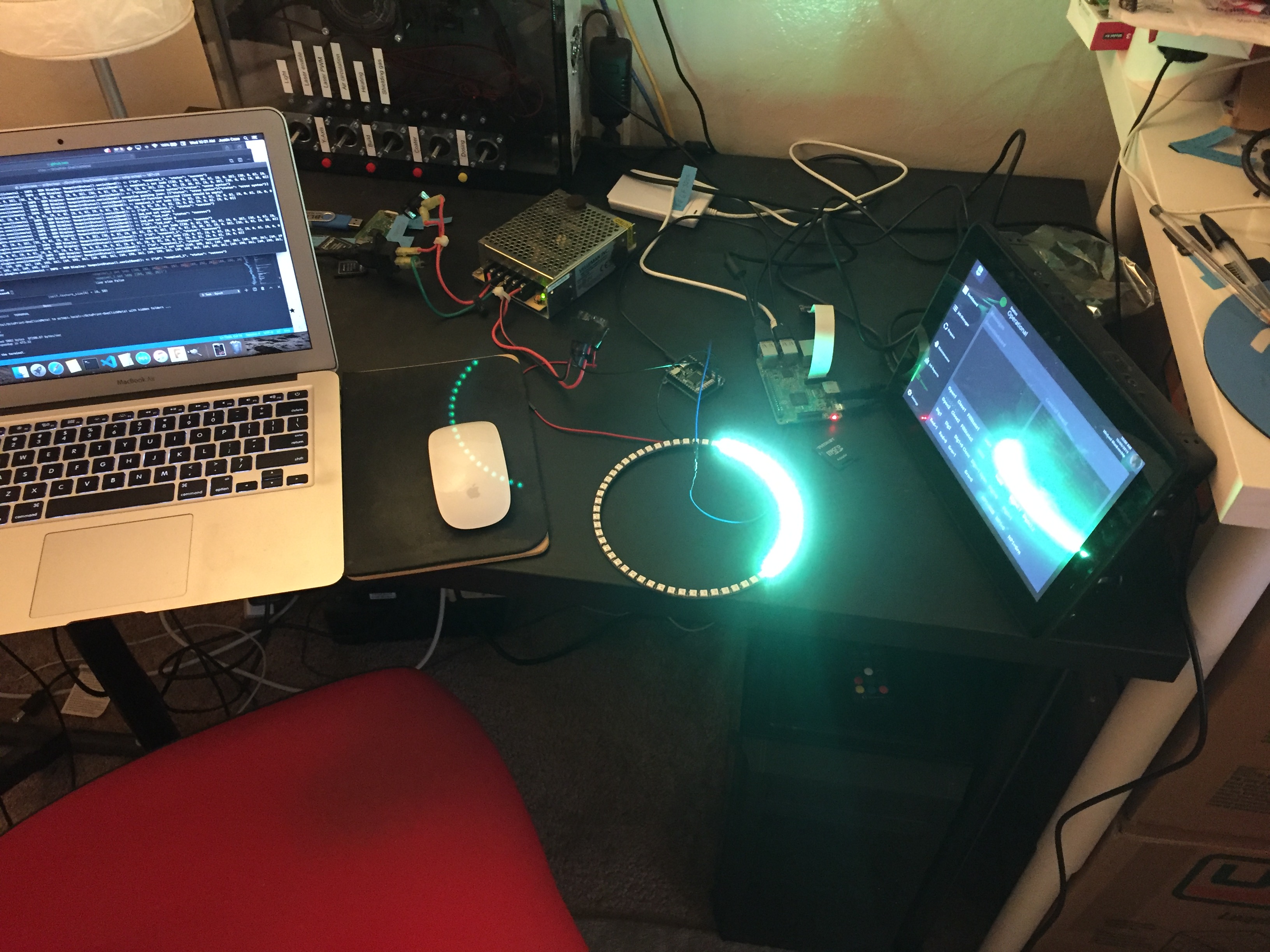
Behind-the-scenes, this is responsible for displaying the print job status and the Cylon animation effect for demos (look at the horizontal space below the green doors):