Size reported in Octoprint doesn't match actual size of model

What is the problem?

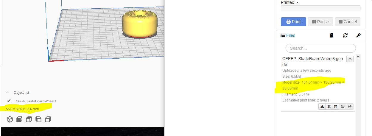
I noticed that the model size reported in Octoprint (x and y axis) is much larger than the actual model shown in Cura. The model in Cura is 56mm x 56mm x 33.6 however in Octoprint it shows 161.51mm x 136.20mm x 33.63

The model prints normally and the correct size just the size shown in the window when looking at the details in Octoprint seems way off.

What did you already try to solve it?

I re-sliced the model and re-uploaded it. No difference.

Have you tried running in safe mode?

Yes. Same dimensions shown

Did running in safe mode solve the problem?

No.

Systeminfo Bundle

You can download this in OctoPrint's System Information dialog ... no bundle, no support!)
octoprint-systeminfo-20220807203303.zip (70.4 KB)

WRITE HERE

Additional information about your setup

OctoPrint version 1.8.1, OctoPi version 0.18.0, Taz6, firmware, Firefox, Windows 10 ... as much data as possible

WRITE HERE

The shown size in OctoPrint incudes all the features the slicer adds to the model: Rafts, purge lines etc.

1 Like

Please share the gcode file so we can look.

GCode attached. I had to use a zip file due to only allowing 4mb in upload.
CFFFP_SkateBoardWheel3.zip (1.5 MB)

I looked at the supplied gcode, determined that @pldugan has a LulzBot TAZ 6, same as me.

Using what @Ewald_Ikemann said, I theorized that the nozzle wipe sequence and the moves to probe points in the start gcode were being counted when determining the min and max X and Y. With the current TAZ 6 firmware, all of these moves in the start gcode can be eliminated.

After that failed to fix the issue, I found more moves in the end gcode and removed those.

That didn't fix the issue either but after a few other experiments and I discovered that the model size in the file list doesn't match the model size in the GCode Viewer.

My conclusion is that there may be a bug in OctoPrint. More investigation is warranted.

The model size seems to be calculated including the origin point. Cura has injected this in the top of the gcode file:

;MAXX:161.512
;MAXY:136.196
;MAXZ:33.625

So the size reported by the server side analysis is pretty much this.

The reason for this that I can guess is the start gcode - immediately at the beginning there is this:

G28 ; Home all axis
G1 E-30 F100 ; retract filament

So OctoPrint considers that 'there was some extrusion' at the origin (my suspicion from what I know of the gcode analyzer), so it is included in the model size in the UI.

What is curious to me is that the GCode Viewer gets it "right" while the gcode analyzer gets it "wrong" when both are looking at the same gcode file.

Is there some logic in the viewer that might be moved to the analyzer?

I assume, a model viewer focuses on the model, OctoPrint on everything that goes to the print bed.

I've not looked t the code, but I'm not convinced that OctoPrint looks at things like the G28. After all, even with a prime line, it might not start at 0,0. Code sliced for a delta might have negative values for the minima. Most slicers put the prime line some way in from the edges, so measuring from the home position makes no sense.

I thought OctoPrint read the dimensions from the MAXX, MAXY etc values in the comments (if present), and those comments have values for MINX and MINY as well. Surely it would make sense to use those...

;FLAVOR:Marlin
;TIME:8591
;Filament used: 3.5103m
;Layer height: 0.125
;MINX:106.014
;MINY:80.698
;MINZ:0.25
;MAXX:161.512
;MAXY:136.196
;MAXZ:33.625

It does, I have looked at the code. When there is a G28, current position is reset, which is sensible because that is exactly what a G28 is doing for the printer as well.

However, I since looked closer at the gcode interpreter code & this gcode in question, and the negative extrusion is not the cause of recording the min/max position. It is slightly further on in the file, as extrusion must be positive & on a move of another axis to be recorded as part of the min/max. Explanation with the << comments.

G1 E-30 F100 ; retract filament  << Current E position is -30
... then some wipe sequence, no E movement
G1 X0 Y0 Z15 F5000 ; move up off last probe point  << Current X/Y position is definitely 0,0
... some heating commands, no movement
G1 Z2 E0 F75 ; prime tiny bit of filament into the nozzle  << Current E position is now 0, which means +30mm of extrusion at 0,0.

So my theory was correct, the commands listed were not quite.

If you were to write a gcode like this:

G28
G1 X100 Y100 E5

Then it would draw a line from the home position to X100 Y100, the line has a minimum 0,0 maximum 100,100

If you wrote gcode like this:

G28
G1 X50 Y50
G1 X100 Y100 E5

The line is drawn 50 -> 100, so minimum 50,50 maximum 100,100. This is how prime lines are usually done - move to the position first, then draw the line.

It doesn't, because there is no standard to how the comments in the gcode file are laid out. Different slicers, different versions of slicers, there is no way to reliably parse the information.

This topic was automatically closed 90 days after the last reply. New replies are no longer allowed.