Apologies if this should be under Plugins, not 100% where it needed to go so went her as a stating point.
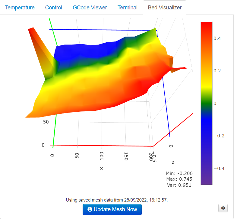
When I run the Update Mesh Now from the Bed Visualiser it comes back with something that looks fairly hideous. In case the picture I'm trying to post doesn't appear it's also available here (google docs) Min is -.206 max is .745 so I'm nearly 1mm out. Looking at the graph I think that it's low on the far left corner (0,220) and high on the front right (220,0).
However, it doesn't seem to matter how slowly I wind the nuts, what I do doesn't seem to impact the graph how I expect it too. I think the nut and bolt are a 1mm pitch so in my head, looking at that picture I need to turn the back left screw anti(counter) clock about 1/4 turn and the front right half a turn clockwise (just less).
I'm also slightly confused as to whether or not generating the mesh will automatically save it and how once it is saved I make sure the printer uses the mesh to auto adjust.
If anyone is able to confirm or point me to where I need to look to work it out I would really appreciate it.
It's possible that you are also adjusting the wrong screw if you haven't oriented the visualization to the real world. What I typically recommend to people is manually level your bed first the old school way with paper/feeler gauge. Then place something with some thickness in the front right corner and run an update mesh process. This will then tell you if the plugin is rendering correctly. If the bump doesn't show in the graph in the front right use the various flip options in the plugin's settings to account for that.
Thanks for the pointers guys. @jneilliii I'll try your suggestion to make sure the visualisation is the correct way round. Presumably a few sticky notes or a couple of business cards would be the best plan.
@Ewald_Ikemann in settings -> Bed Visualizer -> collection I have;
M140 S60 ; starting by heating the bed for nominal mesh accuracy
M117 Homing all axes ; send message to printer display
G28      ; home all axes
M117 Heating the bed ; send message to printer display
M190 S60 ; waiting until the bed is fully warmed up
M300 S1000 P500 ; chirp to indicate bed mesh levels is initializing
M117 Creating the bed mesh levels ; send message to printer display
M155 S30 ; reduce temperature reporting rate to reduce output pollution
@BEDLEVELVISUALIZER	; tell the plugin to watch for reported mesh
G29 T	   ; run bilinear probing
M155 S3  ; reset temperature reporting
M140 S0 ; cooling down the bed
M300 S440 P200 ; make calibration completed tones
M300 S660 P250
M300 S880 P300
M117 Bed mesh levels completed ; send message to printer display
and "save mesh" ticked (which I guess answers one of my questions!)
Your code will not save the mesh to EEPROM. the option to save is a setting to store the mesh in the plugin's settings so it doesn't run the update mesh code every time you switch to the tab. If you want to save mesh and your printer supports it, you need to add a M500 to the update mesh code.
Ok, I understand that I add M500 to the end of the collection G Code to save the current mesh.
Q1. How do I then test if my printer supports saving and if the saved values are restored after a restart.
Q2. Do I need to do anything at the start of each print to make the printer use the mesh or will it just do so automatically if it's been saved / restored with M500?
M115 may potentially give you some insight as to what's enabled in firmware (if capabilities reporting is enabled at least). If saving mesh to EEPROM is possible, then you would have to use a command to activate that mesh. There are some options like RESTORE_LEVELING_AFTER_G28 or something like that in Marlin that could be enabled otherwise after a G28 command you have to activate leveling/mesh. I think the command is M420 S, see the notes section in link below.
Brilliant, thanks. Yes, it looks like I do have RESTORE_LEVELING_AFTER_G28 as if I disable with M420 S0 then run G28 then check M420 again it shows as enabled. Good news. M500 also shows what I think is the points for the grid and they are retained over a power cycle.
But...
(and if this becomes a "wrong forum mate" then please say)
I'm still struggling. I'm using Mick from teaching tech's calibration tutorial (here if you have not seen it) and I dialled the Z offset in at the centre of the bed. It now prints beautifully in the 0,0 corner but it then goes horribly wrong in the centre and other corners.
I would have thought that if Z offset is correct and works at 0,0 and bed levelling is enabled then it should be right everywhere. Am I missing something fundamental here?
No, your assumptions are correct. If offset is correct and the mesh is correct and enabled then as the nozzle moves around the bed it should raise and lower appropriately based on the mesh surface. With the assumption that none of the screws loosened or adjustments made after probing, etc.
So that's kind of good news in that what I thought should be happening is correct but also bad news as that's not what I'm seeing.
Can anyone think why this is going wrong. My process is;
Run update mesh through bed visualiser in octopi
Heat bed to 60 and tool to 150
run G1 X110 Y110 Z0 and check that I can just slip a sheet of paper under the nozzle.
Print test squares as generated from above mentioned site.
Front left is good. all others are printing too high
Marlin firmware is designed to do all of this bed leveling stuff (i.e. generating the mesh and using it) without any OctoPrint plugins.
Run update mesh through bed visualiser in octopi
I believe this step is using the plugin and the assumption is that it is doing it correctly.
Can you manually do the G28 and the G29 V4 (with whatever else is needed) and verify that the mesh generated manually is the same as the mesh generated by the plugin?
BTW, you should heat the bed before you generate the mesh. I don't think the nozzle needs to be heated at this point.
The visualiser does pre-heat the bed so that's all taken care of but no I have not tried doing it manually and checking. Will give that a go and report back.
I have always figured that heading the nozzle before setting Z offset is a good idea to allow for any temperature variation although honestly I have no idea how much variation that creates or if it's anywhere near being worth worrying about.
Does anyone know of a way to work out what sort of bed levelling I enabled when I built my firmware? I don't have the source I used any more and I'm wondering if maybe I enabled the wrong type.
I agree. We are discussing two processes, 1) Leveling the bed and 2) Setting the Z-offset.
The bed should be heated for 1 and 2, the nozzle should be heated for 2.
I've run 3 sets of "home, heat to 60, make mesh, get mesh" and I get something like 0.07 variation between the same point on different runs. Does that sound like a reasonable figure?