Using RPi 3B+ with a step down converter.
I set it to 5.2v and I still get the icon of undervoltage.
How much higher can I set it before killing it?
Using RPi 3B+ with a step down converter.
I set it to 5.2v and I still get the icon of undervoltage.
How much higher can I set it before killing it?
'Step down converters' are commonly unable to provide the voltage they say they will consistently under load. You need one rated for a higher current draw than necessary usually to avoid the voltage drop under load. Or use a proper usb power supply.
The other thing with DIY power setups is that often the wires used do not make a good enough connection and have high resistance. The Dupont style connectors are not good enough really for powering a Pi.
I have the official usb power supply. I'm trying to avoid using it.
I do have thin gauge wires, so I'll replace them with thicker ones.
The Dupont terminal used to connect to the header is actually rated for 3A which is sufficient. Most of the pre-crimped jumper cables are using smaller gauge wire which is where things get limited.
I wanted to chime in with an observation and fix I made that seems rock solid.
Note that the Raspberry PI3 series does not have substantial bulk capacitance on its power rails. Saw the undervoltage messages in the system log (dmesg) and also the handy icon. I had a handful of supplies ranging from 1.5 to 8A available - they all measured 5.1 to 5.3V on the Pi itself. And yet still occasionally errored. This implied to me it is a transitory power draw which made me look at the board's bulk capacitors. To my surprise there are no nice little can electrolytics on the Pi. Easy fix. I grabbed a 330ufd 16V out of my parts drawer and tacked soldered it on. No more dips. No more errors. Rock steady.
This is very logical. The wall supply at the other end of that long loop of cable is delayed in its response to the dip. That delay is relative to its switching power supply response time (say 48khz) and the loop of cable. Putting a nice bulk cap on the board means that when the momentary draw needs some extra electrons it can find a nice little bucket within arms reach.
As for heat I have never had the problem but I did put two little fin heatsink on the two larger chips on the board. Just seemed like a nice thing to do for the little guys. You can get a box of multiple sizes and shapes for very little money from Alibaba or Banggood.
Hello @dennisf !
The most PIs run without problem the way they are. But for certain circumstances an additional capacitor on the power rail is a great solution.
There are some regions in the world power grid is not that stable and the usual tiny PSUs can't compensate a drip of volatge.
I agree, a capacitor at the end of the line: The RasPi can help a lot.
Hi,
That's quite interesting.
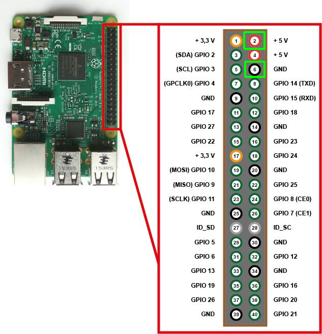
Do you have a picture/diagram to show where one should solder it?
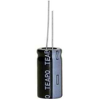
I don't have this capacitor but could other capacitor values help?
Voltage:
16V rate is a good value, 10V is also enough. 6.3V is a bit too close.
Remember: The higher the voltage rating, the larger the size.
Capacitance:
330µF is a good value, but I would not go below 220µF. 470µF is also ok.
Remember: The higher the capacitance, the longer a high current is needed to charge the capacitor when it is discharged. On startup a weak PSU may not be able to handle that. Also: the higher the capacitance, the larger the size too.
Thanks!
But where do I need to solder it on the board?
Electrolytic capacitors are polarized. Take care off the correct connection. the negative side is marked.
Do on your own risk!
Thank you!
do you still power the raspberry pi via USB and only solder the capacitor on the GPIO pins? Or do you have to power the raspberry from the GPIO pins to get the capacitor charging?
Sure, you have still to power the Pi. The capacitor duty is to smooth the voltage drops.
You can either power via USB or connect the USB directly to the GPIO pins. The wires should be thick enough.
But again:
Do on your own risk!
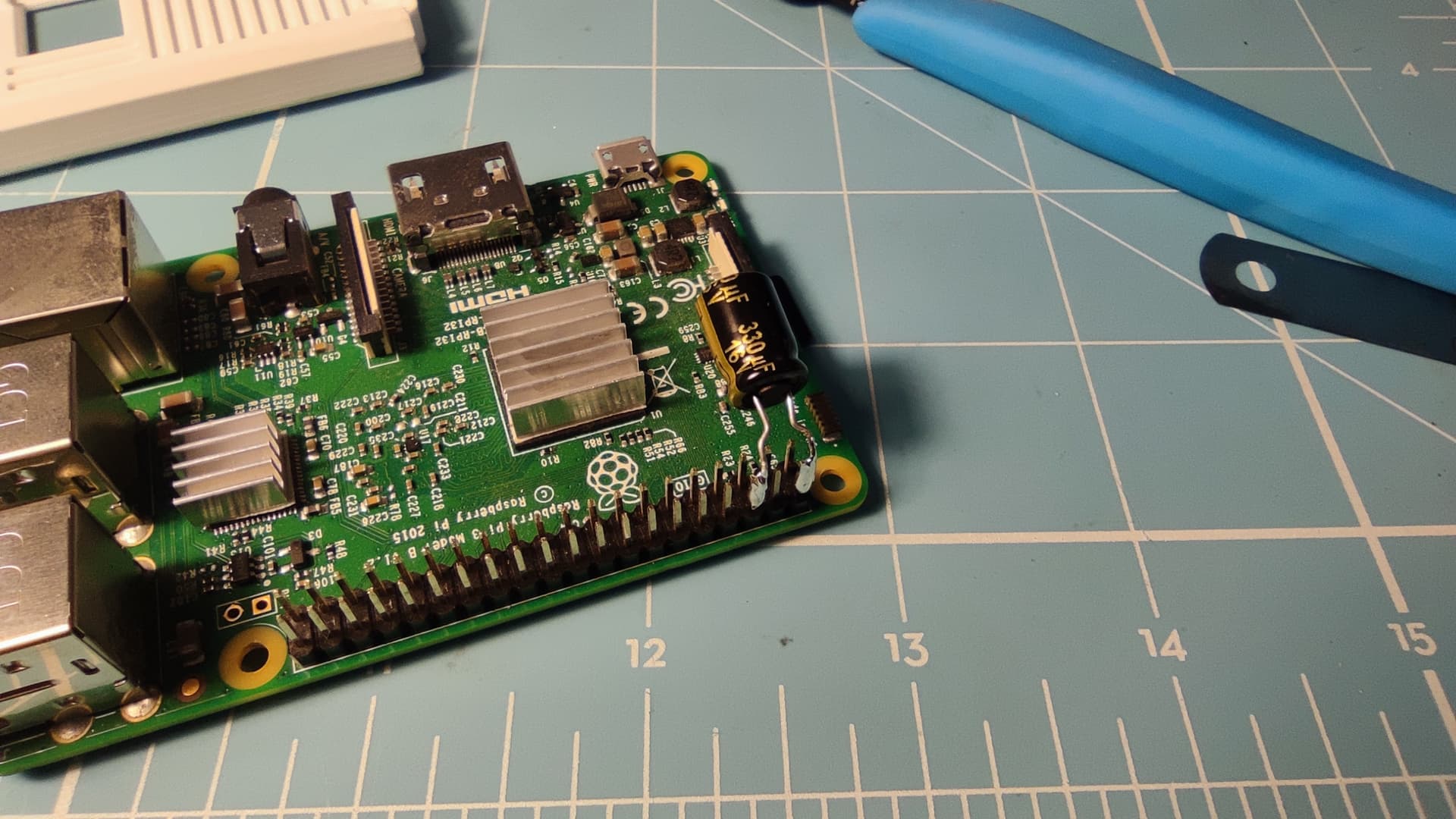
I'd need to take it apart. I just tack soldered the small aluminum can electrolytic across the large diode (D5) with a couple short wires observing polarity. I hot melt glued the capacitor in the open board space to the center of the board.
Note - I just took another Pi3B and was installing HomeAssistant on it. Interesting that it too threw the error with an Octopi image. But the fun observation is when I plugged on the HDMI 5" touchpad LCD (daughter board) the error went away. That board has some capacitance on it too and of course draw a nice additional amount of current. The thought occured to me that it also could be the Pi does not draw a minimum load current for a low grade power supply. So more amusement.
Could we get a picture, please?
As a new user I am limited to one photo upload.
Photo of glued capacitor with flying leads to D5.
Nice! Thanks for sharing.
I'll try to get the 33ufd 16v cap on the GPIO power rails and use the USB connection to power it up. see how it goes.
330ufd - Actually anything 220ufd to 470ufd is fine - you just want a nice large bucket of charge.
I'd think 33ufd is too small.
I did this mod. I soldred a 330uF/16v capacitor on the GPIO and I still get Undervoltage detected.
The RPi is powered via USB port with a stepdown converter set to 5.3v.
You mentioned that the wires should be thick enough. How thick?
And which wires? Are you referring to the wires from the step-down converter?
Thanks.
How much Amps can this one deliver?