Good one. I've been looking for something "north" of 2.5A for a while now.
FWIW never buy something that states to be a charger and a power supply. A charger and a power supply are two different things. A charger needs to provide a stable current it does not have to maintain the 5V on load, it's converted down anyway (in a mobile phone for example). A power supply on the other side must provide a stable voltage level.
It reminds me of the joke:
Q: "What's the difference between a used-car salesman and an electronics-device salesman?"
A: "The used-car sales man knows when he's lying to you."
At some point, you hit the limit of what can be passed through the USB port. At one point, someone told me the standard for USB called for it being able to handle up to 2.4 amps. No idea if that ever was true, let lone if it still holds today. I figured 3 A was just some insurance that the power supply handle the 2.5 A that is recommended.
Ah, that's GREAT! I just ordered that baby up. That's a great find I appreciate your help and advice.
According to the USB-PD standard you can use USB for 5..20V with 5A
For what it is worth...
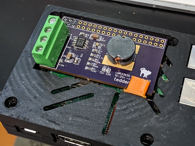
I power my OctoPi from the printer's 24V/12V power supply, using a cheap converter board to drop to 5V. The Pi has power when the printer has power.
Also, fewer wall-warts. 
@John_Mc I got that Northpada PS and all my problems are solved. Thanks so much to everyone on this forum!
Glad it worked out for you. Thanks for reporting back. Nice to have more than just my single data point on the reliability of that supply.
The problem is not an "Undervoltage bug."
To successfully address the problem, you need to deal with the fundamental issue: that being, the Voltage supplying the Raspberry Pi B+.
Measure the actual Voltage being delivered to the Raspberry Pi B+ when the alarm symbol is displayed. Measure the Voltage on pin 4 referenced to pin 6 (GND). You can measure this Voltage with a DVM; It would be more revealing if the measurement is made using an oscilloscope. If you see negative going spikes going less than or equal to 4.75V, the "lightning bolt" alarm symbol WILL appear.
The Under Voltage Alarm system works well, precisely as it is designed to work. There is no "Bug" in it to fix.
How to fix the low Voltage problem:
- Use a low resistance, 5.25V Voltage source capable of delivering 2.50A or greater.
- Make sure there are no unknown resistances in series with the electrical path from the Voltage source to the Raspberry Pi B+. (For example, an inline power switch. The resistance of the switch contacts is an unknown quantity and could cause a significant Voltage drop in the conductive path between the power source and the Raspberry Pi B+.)
To this, I'd add:
- With your multimeter positioned as before, use something like
scporrsync(or upload a huge file via the OctoPrint interface) so that the microSD card is being written to in realtime which will draw more power than the idle condition. - You actually need to exercise all four cores on the Pi as well to see the worst-case scenario.
- Bluetooth, the Ethernet adapter and the wi-fi adapters consume slightly more power when they're active. Exercising them will give you a more accurate picture of the high-water mark for power.
- In many cases, it appears that some controller boards are sinking power over the serial connection. A good test would be done while some activity is occurring on the serial connection.
That was excellent power consumption information.
However, the critical thing to watch is the Voltage level on pin four referenced to pin six (GND). The low Voltage appearing there is what triggers the alarm circuitry, causing the "lightning bolt" symbol to appear on the display screen.
Power consumption increase is irrelevant to the alarm problem; whatever increased the power demand, the power source MUST be able to cover the increased power need. Otherwise, the Voltage available to operate the Pi will necessarily drop, and the low voltage alarm will appear.
Not only that, but it can be super-transient. Unless you have a 'scope with a good falling voltage trigger, 
I get you. A long time ago I designed DC power supplies and amplifiers in one of my Air Force "7-level" classes with all sorts of god-awful charts that we had to create to display the boundary conditions.
I can tell you from experience that with my current development rig the lightning bolt on the display stays on only for the duration of the microSD writing activities.
Good input. Otherwise, you may miss the event that caused the alarm.
It sounds like you went to Keesler AFB, Mississippi for training.
Sounds familiar. I went on a ton of TDY assignments for training over the six years in. 306X2, for what it's worth. I got a plaque from the Pentagon: "Best Teletype Repairman in the Air Force". :laugh:
I spent time at Keesler AFB a long time ago learning Airborne RADAR Repair. I was 18 years old.
Back in the days when you could actually see a single bit of memory. 1981-1987
