I have octopi and ( dash on a pi3b) and I just finished a 2+ day print with the pi at 4 am ) well now I can't get the pi to power on, connect or anything to my pc or the screen on it to load octodash. I just get the red power light and nothing else no text on lcd no response to connections. is it possible I fried the pi overnight after the print finished? I am hoping it not fried and i done smell burnt components.
Do you have the chance to connect a HDMI monitor/TV to he Pi?
If it works, you should get the startup sequqnce.
I can try that ( Monday if I get chance) I work and go straight home to bed the next 2 days.. but I seen it not even power flickering the ender screen when it was plugged in to pi too..
Leave it disconnected from the printers, while powered off, remove and replace the SD card in case it wasn't seated all the way and try again. If it still doesn't boot, the boot messages from above with a monitor will be a good hint.
sadly folks i have to think it died, tried hdmi new card no card,no lcd hooked up everything i can think of outside a microscope and tester (i dont have them lol).. which really7 sucks i think it was only my 3rd time actually using it.once i had it loaded and figuring it out.. I thinking it it over heated ( even with the heatsink and a fan ) or the power plug fried it , ( it would reset if you barely looked at it or bump the desk) it sat on.
unlikely - it got a over-heating-protection and as long as you didn't disable it I don't think that's the case
did you try another psu and if you're using a usb cable to power the pi also another cable?
What kind of USB connection did you use? and what type of printer controller in your 3D printer?
If you can isolate the +5V rail from the USB port on the printer back to the Pi it will save you a lot of trouble. Printers often [for some reason best known to the board designers] feed +12v or +24V back into the +5V rail. This fries the Pi.  There are a number of solutions, cutting the +V wire in the cable or using an isolating plug which doesn't pass the +V rail across is the best solution. Tape is not a good idea, IMO. Good luck.
Differently not often - this is the first time I read about this. Do you have any examples?
1 Like
Indeed. How should the printer even work with 12V on the printer's processor...
There are discussions on port isolation within these forums. Most notably to prevent power drain from the Pi into the control board as per here, Put tape on the 5V pin - Why and how . Maybe its not back power feeding but over current draw - the Pi's internal chipset architecture could result in various components being destroyed as they act as a fuse.. It is not unheard of for MosFets to fail in such a way as to pass the power rail back into the control circuitry. I've been designing and using electronics for over 40 years starting with a PNP transitorised voltage controller, the decisions made in the design of stock control boards is all about minimising cost, and historically, Chinese electronics has been vulnerable to mains spikes so I would rather assume the worst and take appropriate precautions.
The Anet A8 stock board has certainly been implicated in blowing Pi's up, I have an A8 and it was the first machine I put a 5V rail isolator on, now its just part of my standard build. Clearly if the control board is a Ramps on an Arduino this doesn't apply and the USB port can be considered 'safe', I just don't want the aggravation of a blown Pi, so the isolator stays!.
The Anet A8 is 12V, so it can only put 12V through the port, but YMMV, all my other printers are 24V.
Sorry, this is rubbish.
This is the schematics of the A8:

As you see, there a voltage regulators:
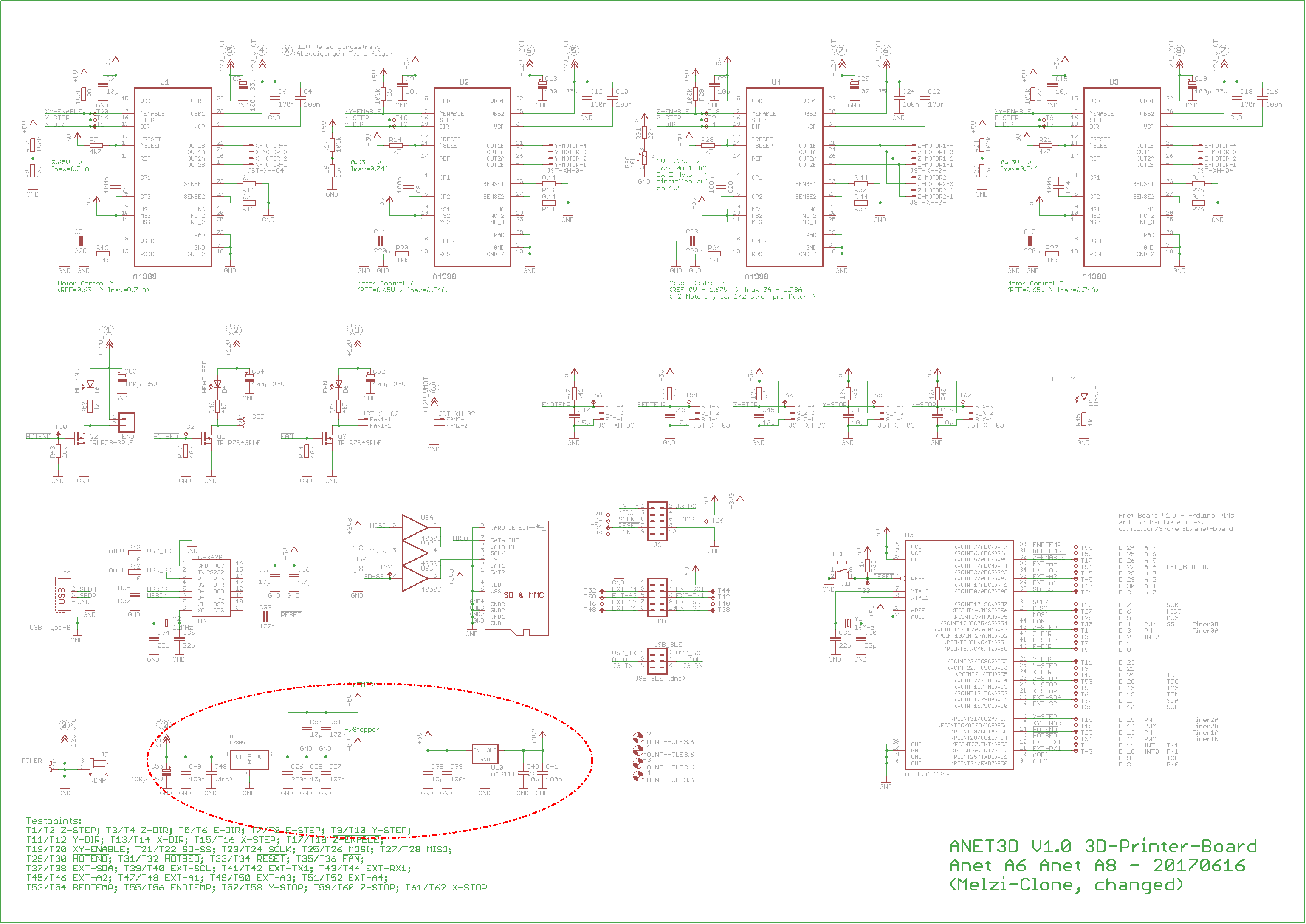
So: 5V for the USB port
Fair point, when I find the content I read a couple of years back I'll post the link here. I got my A8 in late 2018 so between November 2018 and around July 2019 I have read something, somewhere. Just can't remember where.. Actually that schematic is much more interesting as the USB port to the left of the dotted ellipse suggests Pin1 isn't connected at all, as the A8 is a modders paradise, it wouldn't surprise me if the report was caused not by the A8 board, but by errors made on the part of the modder.
1 Like
There actually have been reports of the Creality CR6se feeding 24v on the USB's 5V pin. Those have not been widespread, and in general this has by far not been reported enough from any printer to justify saying that printers "often" do this.
I know it's after the fact, but after I've personally took down an entire home-office (PC, devices, even my UPS died) powering up an AC device connected to my serial port, I've been using really good opto-isolated USB ports:
My current favorite is the uArt, well designed and can handle kilovolts
I've got several of these; I use them to connect to anything AC powered. So some speaker platforms and also my Qidi
There's been more than one time I've shot sparks from the device I'm connected to and my computer just keeps humming along.
I absolutely agree, I must learn not to answer questions close to midnight, entirely my fault for not choosing my words carefully and checking before hitting the reply button. So apologies for my carelessness... #goesawayandhidesincorner. And I DO have a CR6SE, which probably explains the brain fade and inability to quote the source.. Mine is one of the crowdfunded early ones, but I've had no issues at all, unlike some of the very early recipients.
1 Like
This might or might not be relevant, but: Not all voltage regulators can handle a situation where they are not fully in control of the output voltage. So if one regulator is trying to push the USB nominal 5V to 5.1V and the other is trying to pull it to 4.9V, results can be bad. I’ve seen regulators fail on this (not on USB, I don’t work with it, but in general). I haven’t seen a regulator fail to short circuit from input to output, but I guess it is possible.
The scenarios I have read of are the +V, controlled power, shorting to the control input, thus possibly back feeding +12 or +24V back into the I/O. I got some logic level MosFets purely to control a bigger MosFet, or a Relay, Automotive [lorry] relays are 24V, they are easy to get hold of, but I wouldn't switch them from a GPIO pin without something to isolate the coil back EMF on switch-off, the logic level MosFet does that.
I'll recommend to insert an opto-coupler too.
1 Like
I like that idea, I was using opto-isolation about 35 years ago in hazardous environments - paint solvent loaded atmospheres. We should get in the habit of using opto-isolators in machine control environments, it might save our Pi's, and our bacon.
1 Like