First of all this whole tutorial isn't a mandatory mod - you just need it if you run into issues (weird things are happening and you've already ruled out the more common suspects) or if the always running fan and illuminated display (even when the printer is turned off) disturbes you.
I'm starting with the why part:
If you connect a 3D printer via USB to your Raspberry Pi it can lead to all sorts of power related issues.
Most of the time those issues occur only if you turn on your pi before you turn your printer on or if you turn your printer off while the pi is running.
Which issues can occur when you got an USB related power issue?
Unfortunately it can lead to all sorts of problems - here some examples:
What we see most common are undervoltage warnings, unstable Wifi, non working or freezing cameras and disconnecting/malfunctioning USB devices.
We also had some indefinable problems like the print ending mid print which are difficult to diagnose because they could have different causes.
Printer models we've so far seen this reported for are:
Creality Ender 3 Pro (8-bit board)
Creality Ender 5 Plus
Vivendo T-Rex 3
How can I prevent this issues from happen?
That's pretty easy
You simply cut a small stripe of tape and put it on the 5V pin of your USB plug.
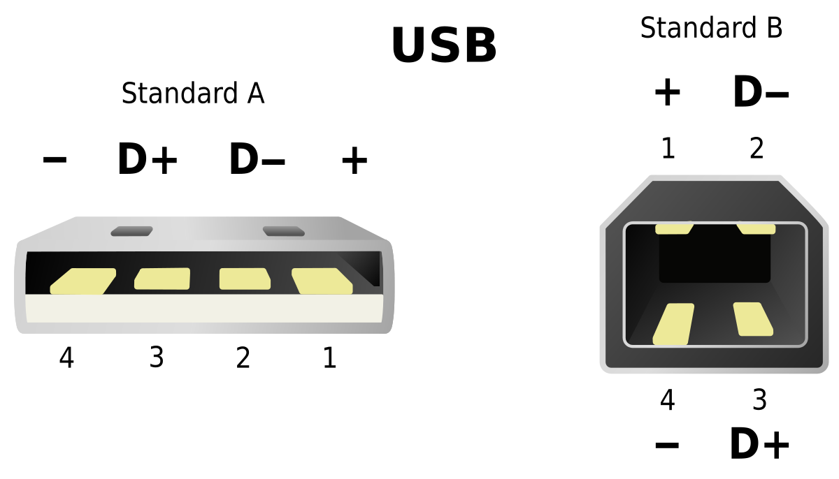
Here you see an image of the standard USB A and B plugs.
Pin 1 is the 5V pin which you're going to cover with the tape.
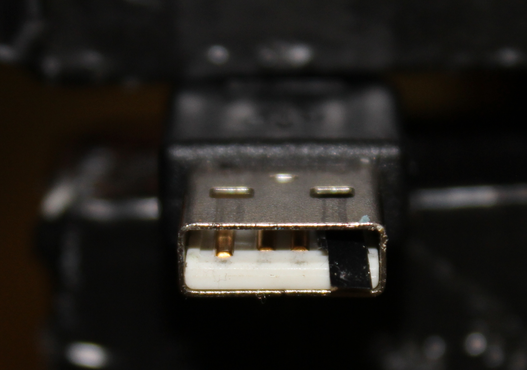
Here two pictures if you feel unsure what to do:
Cut a stripe of tape and grab it with a pair of tweezers.
I like to let the tape overlap a bit so it doesn't move when the pins of the USB port connect to the pins of the plug.
Important: Only tape the 5V pin. The two data pins and ground all need to stay connected!
What happens if you do it wrong?
Don't worry - the worst that can happen is that you can't connect to your printer anymore because you covered the wrong pin(s). Just remove the tape and put it on the right place and it will work again
Does this work for any printer?
While it will work for the most printers there are some exceptions. Those printers need the 5V or the printer won't connect to your pi. The only printer I know for this exception is the BQ Hephestos 2 but there might be more.
For this low of a voltage, I would highly doubt any type of issues. And any non metal tape would be a good enough insulator. That said, electrical tape would probably be best because of its stickiness.
Ultimately, I think a smart-cable or smart-adapter approach makes sense. I worked on one of those yesterday with a lot of fussy soldering to tiny wires.
Yeah but they're not necessarily shielded and the wires are usually tiny. I don't know of anyone now who sources a great solution for this to be honest. I've spec'd things to Adafruit and have asked them to come up with something.
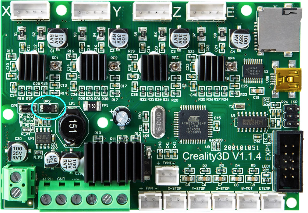
If you have a Creality Ender 3 mainboard, you can simply remove diode DP2 to prevent the Pi supplying power to the board. If you would like to be able to flash the firmware without the mainboard being powered by the power supply, you can also disconnect one side of the diode and add a switch in between. That way you can choose if the Pi should send power to the board or not. Ender_3_Mainboard_altered|690x476
I ended up buying a cheap USB extension cable, cutting it open and I removed a piece of the 5v wire. A little nicer than the tape option IMO, but less permanent than soldering, but it does look a little messy!
There is probably a reason this is a bad idea but I kill the power to my usb via software to prevent "backfeeding" the motherboard.
Stop and start the usb power respectively:
$echo '1-1' | sudo tee /sys/bus/usb/drivers/usb/unbind
$echo '1-1' | sudo tee /sys/bus/usb/drivers/usb/bind
Copypasta example to register everything with Octoprint stop power at boot and use an external relay for main power
/home/pi/scripts/powerPrinter.py
#!/usr/bin/python

#import modules
import RPi.GPIO as GPIO
import sys
#Set to pin connected to relay
pin = 18
usage = "start|stop"
try:
  GPIO.setwarnings(False)
  GPIO.setmode(GPIO.BCM)
  GPIO.setup(pin,GPIO.OUT)
  # check arguments and act
  if sys.argv[1] == "start":
    GPIO.output(pin,0)
  elif sys.argv[1] == "stop":
    GPIO.output(pin,1)
  else :
    print usage
except:
  print "error"
2 /home/pi/scripts/powerPrinter
#!/bin/bash
# Start / stop printer

case "$1" in
    start)
        #start the main power
        /home/pi/scripts/powerPrinter.py start
        #start the usb power
        echo '1-1' | sudo tee /sys/bus/usb/drivers/usb/bind
        echo "$0: started"
        exit 0
        ;;
    stop)
        #stop the usb power first to prevent
        #powing the board and LCD from the Pi
        echo '1-1' | sudo tee /sys/bus/usb/drivers/usb/unbind
        #stop the main power by turning off the relay
        /home/pi/scripts/powerPrinter.py stop
        echo "$0: stopped"
        exit 0
        ;;
    *)
        echo "Usage: $0 {start|stop}" >&2
        exit 1
        ;;
esac
I'm fairly certain it does however the pi for my printer is dedicated and only has the printer connected to USB so this process works for me.
On a related project I need to write a UDEV rule to automount a usb drive and decrypt a volume with the key on the the drive. First attempt didn't work as hoped so I'll probably be reading up on USB bus stuff and may be able to refine this procedure.
Everybody using a Pi pretty much has this problem, get one of these, https://www.tindie.com/products/brianlough/power-blough-r/
Problem solved - Brian made this device specifically to disconnect the +5 feed from the Pi's USB port. It works I have a couple of these, but need some more.. one for each Octoprint printer. I do not like cutting cables, this is perfect.


