Power. All the power. Relays, buck converters, WiFi power plugs

What is the problem? Power management. I don't have a problem as much as looking for solid information on putting several theories of thought together to make a solution.

What did you already try to solve it? I haven't done anything, yet, outside of research to resolve it. My resolution is really these awesome community members who are far more knowledgeable than I.

Additional information about your setup (OctoPrint version, OctoPi version, printer, firmware, what kind of hardware precisely, ...)

I'm running:
OctoPi 0.16.0
OctoPrint 1.3.12
Ender 3 - Stock hardware with printed items
Klipper firmware
Raspberry Pi 3 version 1.2

Alright, I have come along way in the past month with this machine and I am looking for a good power management solution. I have a thought and I am curious if it sounds hoaky before I go cutting into wires that I can't uncut.

I am currently running my Ender 3 through the HS100 WiFi power plug. The raspi is plugged into a surge protector. I have set up remote capability behind a reverse proxy that is password protected. I feel relatively safe with that part. That said, when I am not home, I can kill the outlet power to the printer via Octoprint and jneilliii's awesome TPLink plugin.

Like others, I experience the minor powerback to the printer from the raspi, and I don't like that. I am also experiencing under voltage on the raspi, which I am assuming from reading other posts, is related to that powerback at some point. I have the Canakit power supply that is often mentioned and it might just be old, it could be the limit on USB. It's probably both.

I have seen several tutorials and watched many videos on splicing the power supply to feed power to the raspi from the Ender, via buck converters. I have also seen tutorials and such on adding relays to power the Ender on via the raspi. I want to put both of those together, feed the main power off the WiFi plug. The thought is, I can power down the Ender via Octoprint, I can then power down the raspi with the TPLink plugin, on a countdown. Then, if I want to power it on, remotely, I can use the phone app for TPLink to bring it all back online, since raspi was safely shutdown.

Is this insane or will it work?

Thank you for reading and for any possible information you might be able to pass along my way!

One straightforward solution that I use on my printer is to plug an Ikea KOPPLA power strip into that TP-Link SmartPlug device. I then have three power outlets: the printer's power brick, the Raspberry Pi's power adapter and a spare.

So the trick is to gracefully shutdown the Pi then toggle off power to the TP-Link. So now, you don't have to fuss with the enclosure plugin, back-powering the printer board through the Pi or anything like that.

When the TP-Link is powered on, all the devices come on at the same time and no problem.

UPDATE: I also now use jneiliii's excellent TPLinkSmartplug plugin. This allows me to just select the option from the statusbar (or via the pseudo gcode) to gracefully shutdown OctoPrint/Raspbian and then throw a delayed toggle to any of the TPLink products I own.

2 Likes

I'm in the process of setting up a Sonoff Basic (with tasmota firmware) to control my Ender 5. The Pi running Octoprint is powered from the printer power supply via a 5V buck converter. The Pi runs with a super capacitor based UPS that will allow it to turn the power off and then shutdown correctly. Only one power point required.
I had planned to put the Sonoff in the printer electronics enclosure until I realized it's all metal which acts very well as a wifi shield :slight_smile:

2 Likes

Another option would be one of the multi-port tp-link smart devices. Like the HS300 or the more affordable 2 plug HS107 device. But I don't think that's going to resolve the back-powering issue of USB on the ender 3 I think @krykiett is talking about.

2 Likes

That is a solution I didn't even consider.

I think in this scenario I still need to determine if the power adapter for the Pi is a piece of crap or not, but that is an easier venue to pursue.

The idea of tearing it apart and hacking it back together seems fun, but I'm also wildly apprehensive, so your solution seems like a better first step.

The only thing that catches me up about it, is that I don't always want to kill Octoprint, but I also don't want that power feedback to the printer. To kill the printer outright, I would also have to kill the Pi. I suppose with this option I would have to make some concession in either direction.

I feel like I might be over complicating this by my almost obsessive need to remove power from the printer, while not in use, while not at home, but still leave access to the Pi at all times, should I want.

And that's part of my problem, it's a multi layered thing.

I'm pretty sure as a result of this under voltage (I believe), I have killed an SD card and had to reinstall the entire operation 3 times. I, also, think I've done some damage to the Pi itself, which I do intend to replace completely. You know, after R&D phase is complete here.

I'm just trying to figure out the most eloquent way to approach this, with limited knowledge overall. I've been pouring over these forums for weeks now and you guys are extremely knowledgeable, helpful, and able to help me see it from angles I didn't consider or even knew existed.

This entire community has been extremely helpful in my process!

Awesome plugins, btw. The TPLink was my first step in this process :slight_smile:

I don't have an issue with back-powering the Pi as I've replcaed my printer controller with an MKS Gen L and TMC drivers.

1 Like

The UPS also seems like a fairly interesting concept to incorporate with this.

I like the way you are thinking, but again like I said in another reply, I'm almost certain I'm over complicating this.

Or maybe I want things beyond what I should. :stuck_out_tongue:

Is the back-powering a stock board thing only? I'm considering the SKR Mini E3 which seems to be doing fairly well so far, but I haven't looked farther into it.

I just assumed the back-power was a constant across all boards and didn't realize it might not exist on some.

Having the back-powered connection from the pi does have a benefit though. It allows you to stay connected to the printer from OctoPrint's perspective and therefore able to use the M80 gcode triggers of my plugin to power on the printer automatically. I don't have an Ender 3, but I like @geoff_s replaced my CR-10's board (albeit with an EinsyRambo) and don't have the back powered issue either.

1 Like

You may find this video helpful...the firmware requires some special tricks with the latest version.

1 Like

Ok, so really, I should consider upgrading the controller board first, which is in the pipeline anyways. In theory that should absolve the concern for the back-power allowing me to go with @OutsourcedGuru 's option.

Do we know what causes the back-power from the Creality boards? Or is this going to be a shot in the dark with whatever controller I decide to go with?

I am still relatively new to this, but it has been fun.

I have watched some of that video, he seems to be really well informed and I enjoy his videos for this stuff. It seems that board has been really good or really bad, with almost no inbetween for most people. I haven't really gone done the controller board hole yet, but I suppose it needs to happen sooner rather than later.

I think I'm going to mark @OutsourcedGuru as the solution, go do some research on controller boards and get one, then give his solution a shot.

Thank you very much, this has been very helpful!

1 Like

The MKS controller requires a hole to be cut for the relocated USB connector and rather than do this, I removed the connector from the PCB and put a header in it's place. I connect a shortened USB cable to the header and just checking shows I don't connect 5V. So perhaps it's not just the stock board that suffers from back-powering. (this is the UPS I'm using)

1 Like

For what it's worth...

  • I've contacted Adafruit and have asked them to either source or custom-build a smart serial adapter or cable suitable for 3D printers in the typical Pi -> Arduino/RAMPS environment. I spec'd the requirements, described the problem and the market opportunities. They received the information and thanked me.
  • I've designed two or three versions of this myself and have purchased the parts at Fry's Electronics perhaps three weeks ago.

One version looks like a printer-side solution: At the Type-B side of things an adapter goes inline and has a 5V lead over to the printer board to detect when that's been turned on. This fires an inline relay for the serial communication's 5V line to make this connect. So if power is on for the Arduino, the 5V line is honored. This would be a dumb (smart?) version. I'm not convinced that this wouldn't be defeated by a race condition in which the Pi provides the 5V power that makes the device think that the printer is powered.

Another version looks like a Pi-side solution: At the Type-A side of things an adapter goes inline and has a GPIO lead over to the Pi board to be programmatically toggled (with suitable discrete components), again closing a relay to permit the 5V line to function. The user then could use a script approach to control the relay.

The final version looks like a serial cable solution: Embedded inside are a pair of relays. The Pi-side relay is controlled by the printer board and vice versa. Think of it as a handshake in which each palm rests on the other person's wrist past their hand. The 5V presence from the printer board's power allows the Pi-side relay to pass the 5V to the center of the cable to then see the printer-side relay. It passes through this second relay if the GPIO-pin on the Pi allows it to do so. To me, it seems to be the smartest-yet-controllable solution.


Of course, adding a smart USB hub which includes a bus to allow the ports to be individually toggled via uhubctl would be another solution. As long as you know the usb device address, you're good to go. The typical buses used by the Raspberry Pi Foundation fail in this, even with the Pi4B.


"Do we know what causes the back-power from the Creality boards?"

To the best of my knowledge, the basic assumption for USB power is that the host was always thought to have the beefy power supply and the device (think USB thumbdrive) never had its own power. The Pi versus Arduino/RAMPS situation completely reverses that paradigm; the RAMPS board has the beefy power requirements and the Pi can't be adequately powered over the constrained 2.1A (in theory) limitation of a micro-USB connection.

1 Like

So I'm not nearly as advanced as you guys but some of that makes good sense to me.

Without the knowledge of this forum, I wouldn't know the way up.

As much as I want to have a good response at this point, your information is going to lead me to read more, so I can understand better. Which I suppose is the point.

I just want to say thank you on behalf of those of us who don't really understand this stuff. I want to learn more and I will, but lots of people just want this stuff to do things they don't understand, and you guys make that happen for us.

I feel inspired by the work you guys do and now it's time to run further down the rabbit hole with this new information.

I saw you also have some USB plugins? Are those intended to work in the capacity that you're talking about?

I'm extremely fascinated with all this info.

By "you", I guess you mean me. Per the README, my USBControl plugin uses the uhubctl executable in an attempt to toggle the 5V power on a Pi's Type A connections. The cheap USB bus for most Pi computers is "ganged", meaning that all four ports will be toggled. This is the latest status regarding the Pi 4B's issue.

Color me "annoyed". To me, it's clear that the average hobbyist wishes to control things and including the more costly USB bus would have been a natural selection if I were the Raspberry Pi Foundation. Personally, I've reached the point where I don't expect a solution from them and I'm now "rolling my own" (in the form of this after-market solution).

Hover over the jumper seen here; it should give you a description. Some boards allow you to decide if the printer board can be back-powered or not via the Type-B connector.

Sorry about that, I thought the reply would work to indicate, but I don't think reply works how I thought. :grin:

Thank you for the information, though. I have a lot to read when I get home from work. I'm very interested in what you've already worked through.

It does now, I changed a forum configuration setting so it should be a bit more clear now.

3 Likes

Awesome! Thank you for your hardwork too!

This is an awesome community.

2 Likes

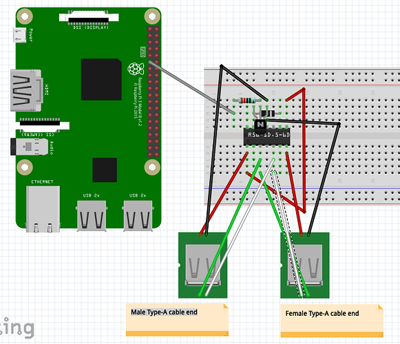
I've managed to build a prototype adapter which appears to work. You basically cut a male/female USB extension cable, tin or otherwise add pins to the four ends of each and then create a small circuit board. I've cut the 5' serial cable down to perhaps 5" in length now so I haven't incorporated any ferrite cores for this or shielding. I might put it all in a metal project box but I don't know yet.

I used the crimp-on connector pins to make this slightly easier but without the crimping tool they're a royal pain. They're supposed to be solderless but I ended up soldering each just to be on the safe side. I should have had the male version but I didn't have them so I ended up robbing some header pins to make all this work. It's probably just easier to tin the ends of the wires instead.

USB-Smart-Cable.fzz.zip (11.6 KB)

Parts

  1. Rhino USB 2.0 A Male to Female cable, model CBU-EXT UPC 854190000827. The package description indicates 59" but the website says 6' so your mileage may vary. $3.99
  2. OSEPP Mini Breadboard, model LS-00017 UPC 899262000428. $6.49 for two, we'll be using just one. = $6.49 (two)
  3. NTE108 T-NPN, Si, RF-IF Amp & Osc transistor UPC 768249009917 = $1.59
  4. R56-1D.5-6D SPST 5V reed relay UPC 768249030379 = $4.69
  5. 1K-ohm resistor = $1.49 (four)
  6. Velleman Female Connector Pins with Strain Relief - 100 Pack = $2.49 (qty 100)

Essentially, the white/green data wires pass through. Note that they're just occupying an unused pair of columns on one half of the breadboard.

The two black (or blue) wires from the USB cable ends land on the middle column on the opposite side of the breadboard as GND. The only other thing common to that column is the emitter of the NPN transistor.

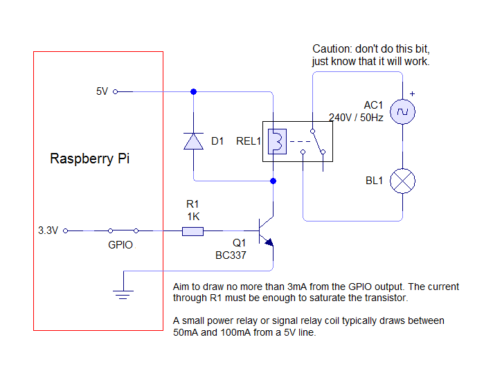
The base of the NPN transistor is married to one end of a 1K resistor. The other end of that goes to GPIO board pin 11 on the Raspberry Pi and is the only wire necessary since GND comes from the male side of the USB connection.

The reed relay chip takes up 14 connections but only two pins are seen in each of the four corners.

Software

echo "17" > /sys/class/gpio/export
echo "out" > /sys/class/gpio/gpio17/direction
echo "1" > /sys/class/gpio/gpio17/value        # Enables the 5V line
echo "0" > /sys/class/gpio/gpio17/value        # Disables the 5V line
echo "17" > /sys/class/gpio/unexport           # Assuming that you want to do this in Python instead

Possibly useful link

It's entirely possible that this particular relay incorporates an internal diode as seen in the PDF linked but it doesn't hurt to add an external one as I've done for the purpose of safety.

Apologies that the Fritzing diagram is a bit tight but there's not a lot of choices for NPN transistors so it wanted to take over the entire space, unfortunately.

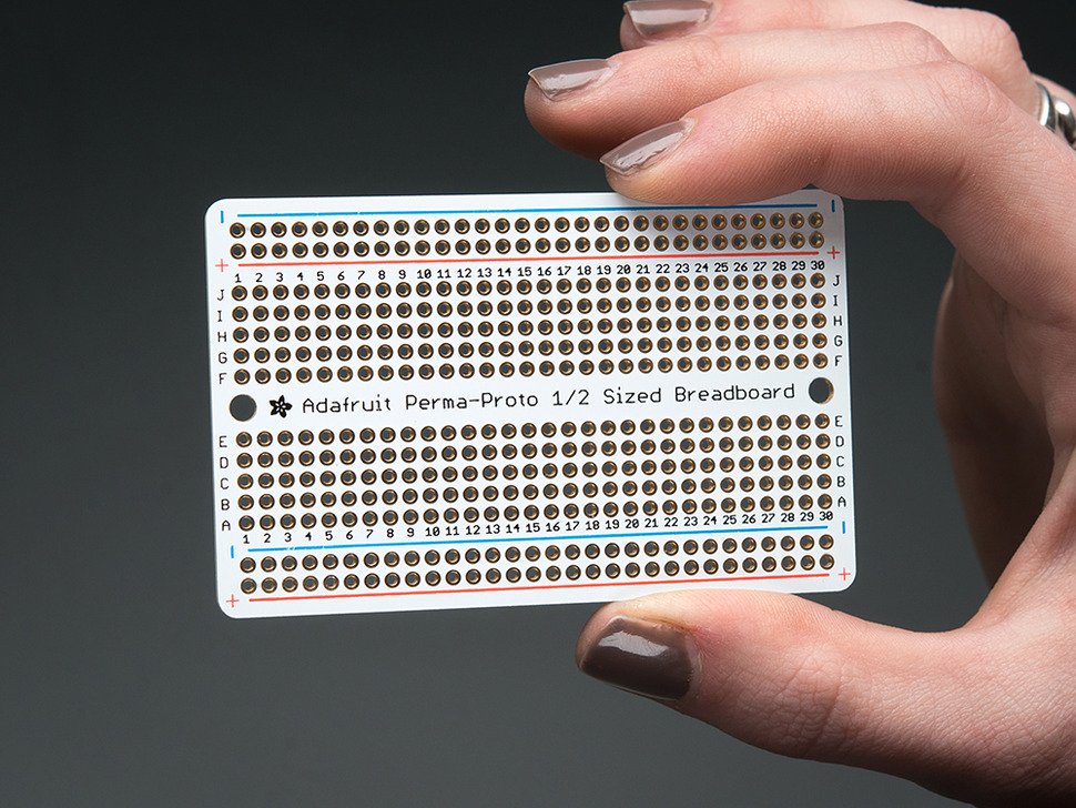
Next, I'll take these parts to an Adafruit Perma-Proto board, I'm guessing. This will then be easier for burn-in testing of everything.

1 Like

you got beautiful nails :brown_heart: