Having the back-powered connection from the pi does have a benefit though. It allows you to stay connected to the printer from OctoPrint's perspective and therefore able to use the M80 gcode triggers of my plugin to power on the printer automatically. I don't have an Ender 3, but I like @geoff_s replaced my CR-10's board (albeit with an EinsyRambo) and don't have the back powered issue either.
1 Like
You may find this video helpful...the firmware requires some special tricks with the latest version.
1 Like
Ok, so really, I should consider upgrading the controller board first, which is in the pipeline anyways. In theory that should absolve the concern for the back-power allowing me to go with @OutsourcedGuru 's option.
Do we know what causes the back-power from the Creality boards? Or is this going to be a shot in the dark with whatever controller I decide to go with?
I am still relatively new to this, but it has been fun.
I have watched some of that video, he seems to be really well informed and I enjoy his videos for this stuff. It seems that board has been really good or really bad, with almost no inbetween for most people. I haven't really gone done the controller board hole yet, but I suppose it needs to happen sooner rather than later.
I think I'm going to mark @OutsourcedGuru as the solution, go do some research on controller boards and get one, then give his solution a shot.
Thank you very much, this has been very helpful!
1 Like
The MKS controller requires a hole to be cut for the relocated USB connector and rather than do this, I removed the connector from the PCB and put a header in it's place. I connect a shortened USB cable to the header and just checking shows I don't connect 5V. So perhaps it's not just the stock board that suffers from back-powering. (this is the UPS I'm using)
1 Like
For what it's worth...
- I've contacted Adafruit and have asked them to either source or custom-build a smart serial adapter or cable suitable for 3D printers in the typical Pi -> Arduino/RAMPS environment. I spec'd the requirements, described the problem and the market opportunities. They received the information and thanked me.
- I've designed two or three versions of this myself and have purchased the parts at Fry's Electronics perhaps three weeks ago.
One version looks like a printer-side solution: At the Type-B side of things an adapter goes inline and has a 5V lead over to the printer board to detect when that's been turned on. This fires an inline relay for the serial communication's 5V line to make this connect. So if power is on for the Arduino, the 5V line is honored. This would be a dumb (smart?) version. I'm not convinced that this wouldn't be defeated by a race condition in which the Pi provides the 5V power that makes the device think that the printer is powered.
Another version looks like a Pi-side solution: At the Type-A side of things an adapter goes inline and has a GPIO lead over to the Pi board to be programmatically toggled (with suitable discrete components), again closing a relay to permit the 5V line to function. The user then could use a script approach to control the relay.
The final version looks like a serial cable solution: Embedded inside are a pair of relays. The Pi-side relay is controlled by the printer board and vice versa. Think of it as a handshake in which each palm rests on the other person's wrist past their hand. The 5V presence from the printer board's power allows the Pi-side relay to pass the 5V to the center of the cable to then see the printer-side relay. It passes through this second relay if the GPIO-pin on the Pi allows it to do so. To me, it seems to be the smartest-yet-controllable solution.
Of course, adding a smart USB hub which includes a bus to allow the ports to be individually toggled via uhubctl would be another solution. As long as you know the usb device address, you're good to go. The typical buses used by the Raspberry Pi Foundation fail in this, even with the Pi4B.
"Do we know what causes the back-power from the Creality boards?"
To the best of my knowledge, the basic assumption for USB power is that the host was always thought to have the beefy power supply and the device (think USB thumbdrive) never had its own power. The Pi versus Arduino/RAMPS situation completely reverses that paradigm; the RAMPS board has the beefy power requirements and the Pi can't be adequately powered over the constrained 2.1A (in theory) limitation of a micro-USB connection.
1 Like
So I'm not nearly as advanced as you guys but some of that makes good sense to me.
Without the knowledge of this forum, I wouldn't know the way up.
As much as I want to have a good response at this point, your information is going to lead me to read more, so I can understand better. Which I suppose is the point.
I just want to say thank you on behalf of those of us who don't really understand this stuff. I want to learn more and I will, but lots of people just want this stuff to do things they don't understand, and you guys make that happen for us.
I feel inspired by the work you guys do and now it's time to run further down the rabbit hole with this new information.
I saw you also have some USB plugins? Are those intended to work in the capacity that you're talking about?
I'm extremely fascinated with all this info.
By "you", I guess you mean me. Per the README, my USBControl plugin uses the uhubctl executable in an attempt to toggle the 5V power on a Pi's Type A connections. The cheap USB bus for most Pi computers is "ganged", meaning that all four ports will be toggled. This is the latest status regarding the Pi 4B's issue.
Color me "annoyed". To me, it's clear that the average hobbyist wishes to control things and including the more costly USB bus would have been a natural selection if I were the Raspberry Pi Foundation. Personally, I've reached the point where I don't expect a solution from them and I'm now "rolling my own" (in the form of this after-market solution).
Hover over the jumper seen here; it should give you a description. Some boards allow you to decide if the printer board can be back-powered or not via the Type-B connector.
Sorry about that, I thought the reply would work to indicate, but I don't think reply works how I thought. 
Thank you for the information, though. I have a lot to read when I get home from work. I'm very interested in what you've already worked through.
It does now, I changed a forum configuration setting so it should be a bit more clear now.
3 Likes
Awesome! Thank you for your hardwork too!
This is an awesome community.
2 Likes
I've managed to build a prototype adapter which appears to work. You basically cut a male/female USB extension cable, tin or otherwise add pins to the four ends of each and then create a small circuit board. I've cut the 5' serial cable down to perhaps 5" in length now so I haven't incorporated any ferrite cores for this or shielding. I might put it all in a metal project box but I don't know yet.
I used the crimp-on connector pins to make this slightly easier but without the crimping tool they're a royal pain. They're supposed to be solderless but I ended up soldering each just to be on the safe side. I should have had the male version but I didn't have them so I ended up robbing some header pins to make all this work. It's probably just easier to tin the ends of the wires instead.
USB-Smart-Cable.fzz.zip (11.6 KB)
Parts
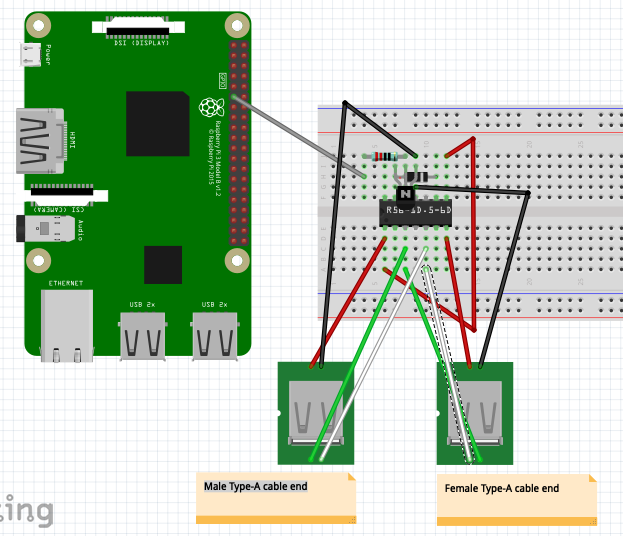
- Rhino USB 2.0 A Male to Female cable, model CBU-EXT UPC 854190000827. The package description indicates 59" but the website says 6' so your mileage may vary. $3.99
- OSEPP Mini Breadboard, model LS-00017 UPC 899262000428. $6.49 for two, we'll be using just one. = $6.49 (two)
- NTE108 T-NPN, Si, RF-IF Amp & Osc transistor UPC 768249009917 = $1.59
- R56-1D.5-6D SPST 5V reed relay UPC 768249030379 = $4.69
- 1K-ohm resistor = $1.49 (four)
- Velleman Female Connector Pins with Strain Relief - 100 Pack = $2.49 (qty 100)
Essentially, the white/green data wires pass through. Note that they're just occupying an unused pair of columns on one half of the breadboard.
The two black (or blue) wires from the USB cable ends land on the middle column on the opposite side of the breadboard as GND. The only other thing common to that column is the emitter of the NPN transistor.
The base of the NPN transistor is married to one end of a 1K resistor. The other end of that goes to GPIO board pin 11 on the Raspberry Pi and is the only wire necessary since GND comes from the male side of the USB connection.
The reed relay chip takes up 14 connections but only two pins are seen in each of the four corners.
Software
echo "17" > /sys/class/gpio/export
echo "out" > /sys/class/gpio/gpio17/direction
echo "1" > /sys/class/gpio/gpio17/value        # Enables the 5V line
echo "0" > /sys/class/gpio/gpio17/value        # Disables the 5V line
echo "17" > /sys/class/gpio/unexport           # Assuming that you want to do this in Python instead
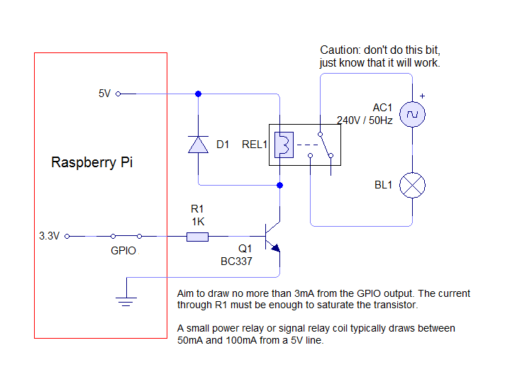
It's entirely possible that this particular relay incorporates an internal diode as seen in the PDF linked but it doesn't hurt to add an external one as I've done for the purpose of safety.
Apologies that the Fritzing diagram is a bit tight but there's not a lot of choices for NPN transistors so it wanted to take over the entire space, unfortunately.
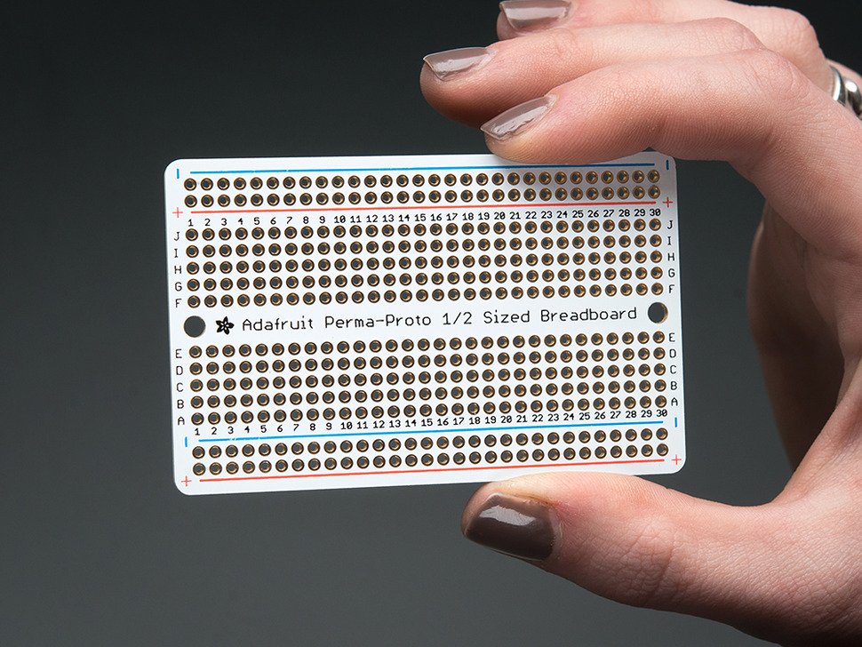
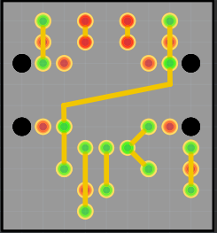
Next, I'll take these parts to an Adafruit Perma-Proto board, I'm guessing. This will then be easier for burn-in testing of everything.
1 Like
you got beautiful nails 
They're probably Ada's, to be honest.
1 Like
I've just ordered three circuit boards for the initial prototype for testing/sizing, for what it's worth. $12.14 for three with tax and shipping. I'd call that a deal.
2 Likes
Shouldn't the diode in the circuit diagram pointing in the other direction?
No, it's correct the way it is. When the relay is switched off, the coil inside creates a current that is opposite the former current, so the voltage is also is reverse. To protect the semiconductors (here the transistor), this voltage is shortened by the diode.
3 Likes
Saved by the diode. (yay)
1 Like
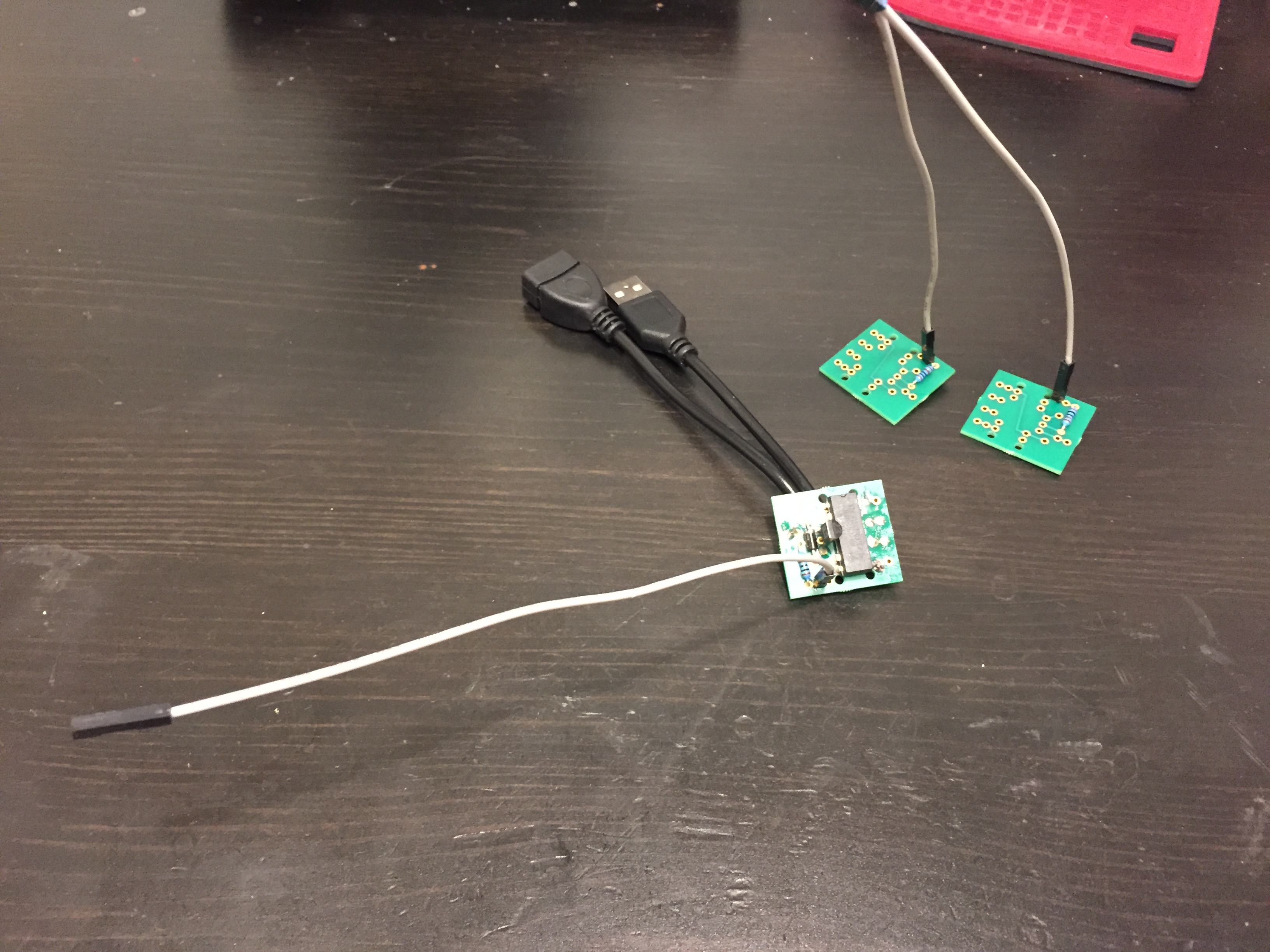
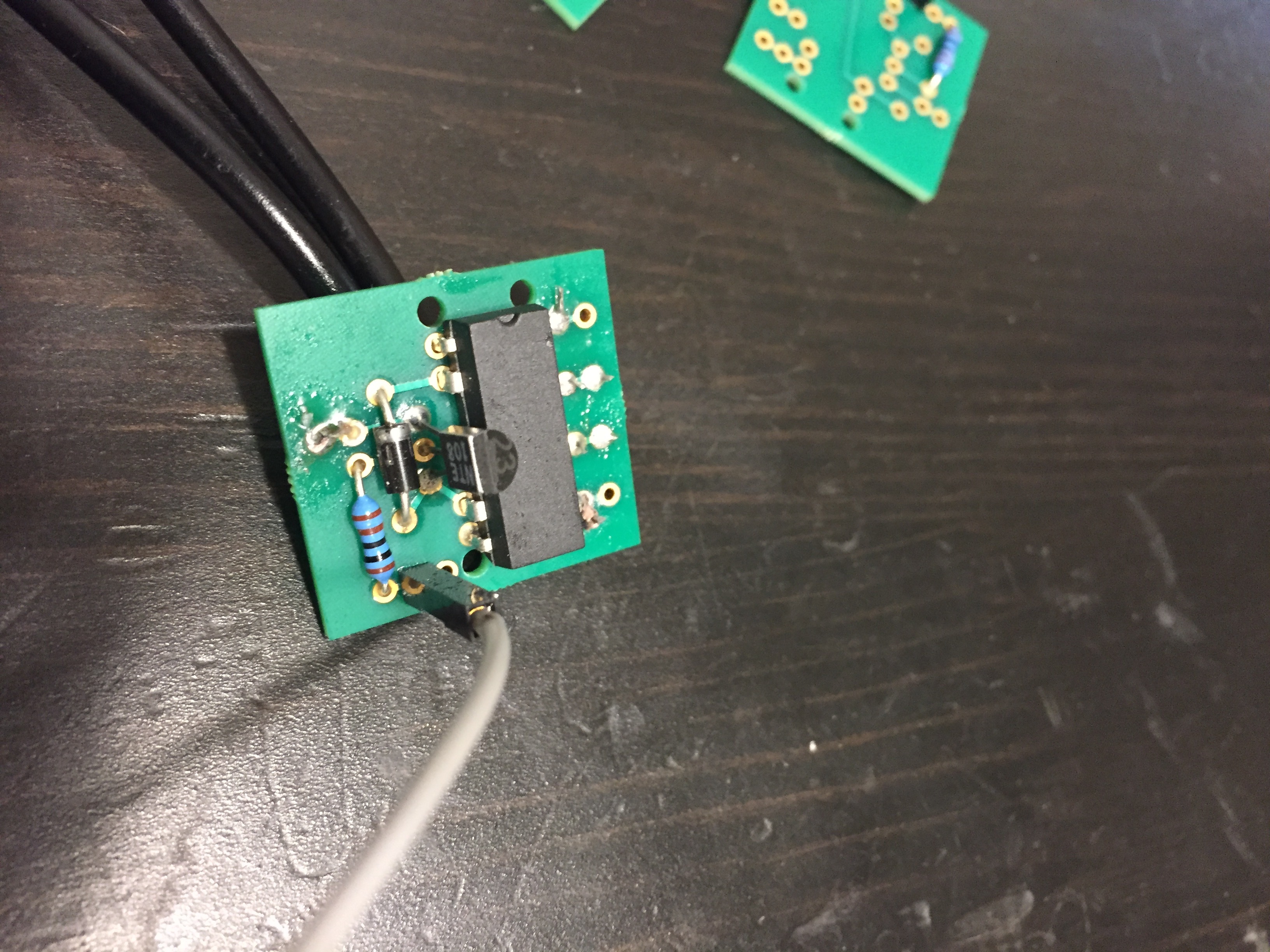
The first group of three prototype boards came in and I just soldered one up since I had the parts from earlier. I'll need some thinner tie wraps to go through those holes for cable management and I suppose I'll now need to design a plastic case. Other than that, it seems to work as expected.
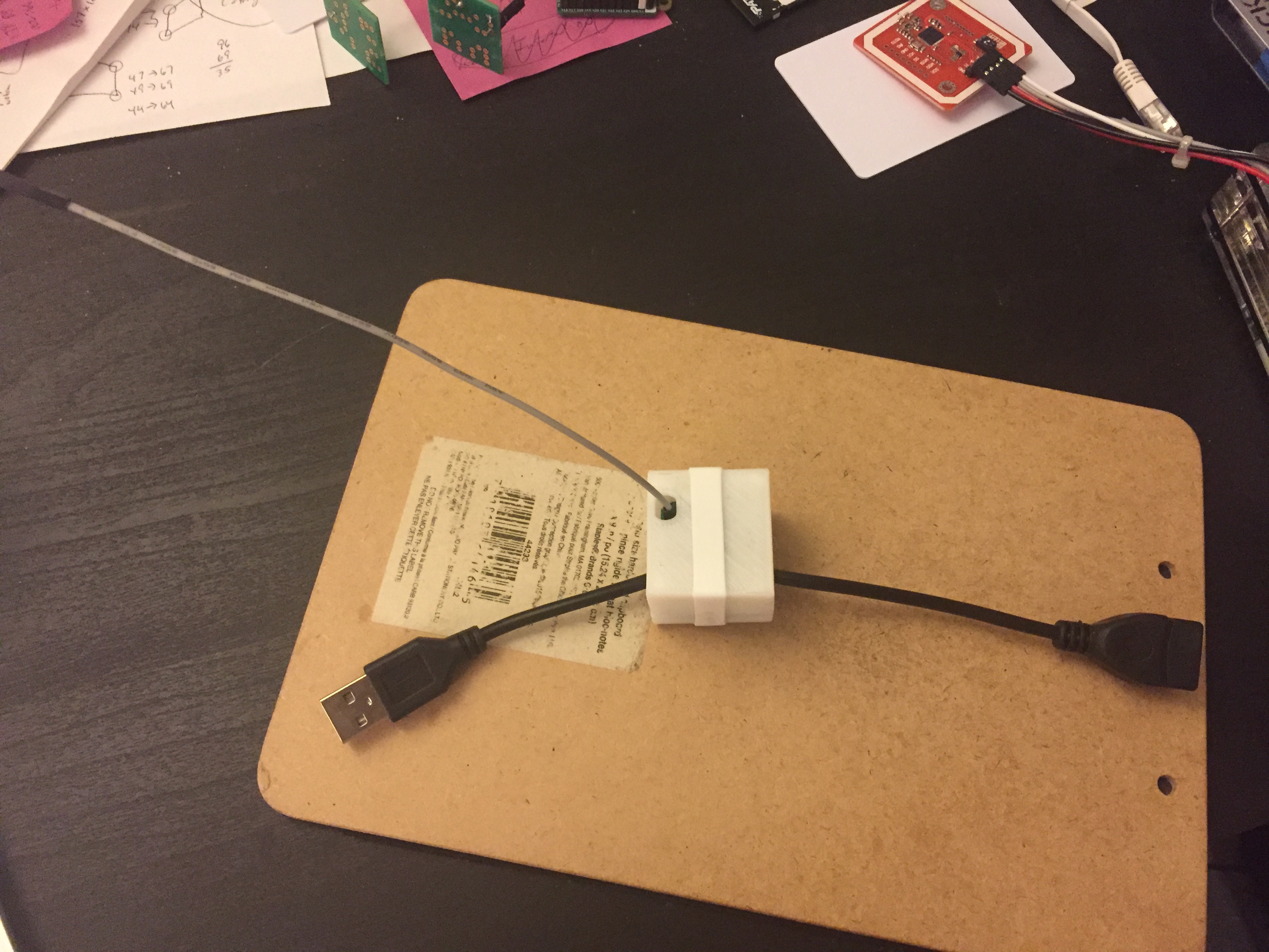
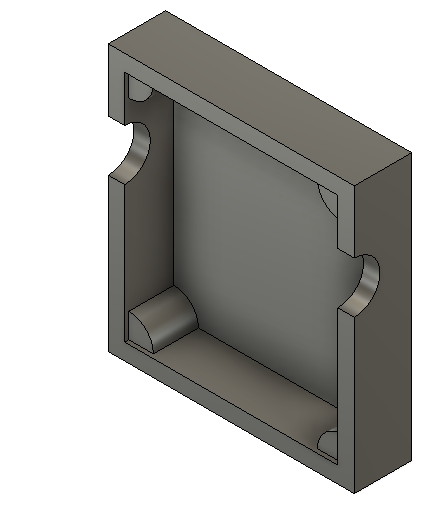
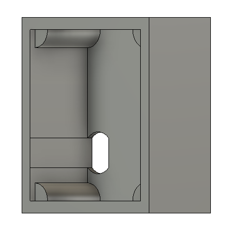
Back from vacation and I've now designed/printed an enclosure. I've used a simple tight rubber band which came on a William Sonoma whisk to hold the two halves together.
- $3.99
- $1.59
- $4.69
- $0.37
- $4.04
- $0.20
- $0.03
$15.00 approximate total cost of parts if you make more than one of them.
1 Like