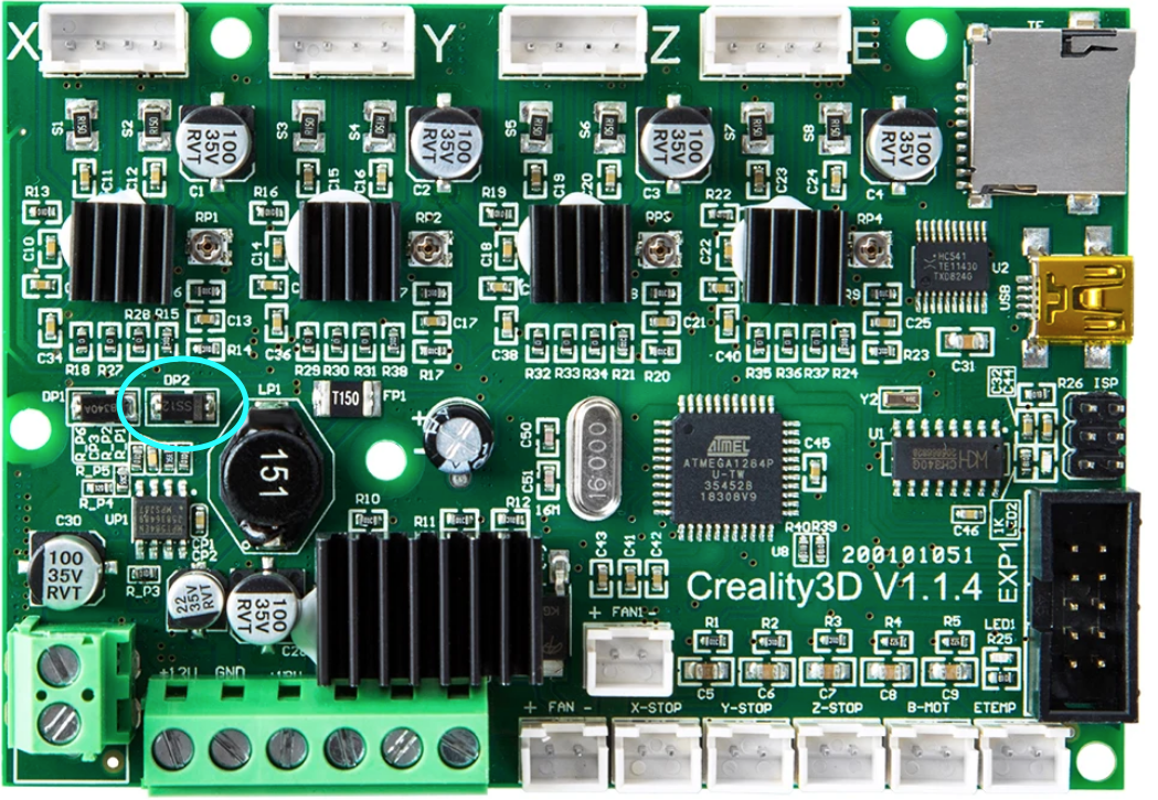
If you have a Creality Ender 3 mainboard, you can simply remove diode DP2 to prevent the Pi supplying power to the board. If you would like to be able to flash the firmware without the mainboard being powered by the power supply, you can also disconnect one side of the diode and add a switch in between. That way you can choose if the Pi should send power to the board or not. Ender_3_Mainboard_altered|690x476
I ended up buying a cheap USB extension cable, cutting it open and I removed a piece of the 5v wire. A little nicer than the tape option IMO, but less permanent than soldering, but it does look a little messy!
There is probably a reason this is a bad idea but I kill the power to my usb via software to prevent "backfeeding" the motherboard.
Stop and start the usb power respectively:
$echo '1-1' | sudo tee /sys/bus/usb/drivers/usb/unbind
$echo '1-1' | sudo tee /sys/bus/usb/drivers/usb/bind
Copypasta example to register everything with Octoprint stop power at boot and use an external relay for main power
/home/pi/scripts/powerPrinter.py
#!/usr/bin/python

#import modules
import RPi.GPIO as GPIO
import sys
#Set to pin connected to relay
pin = 18
usage = "start|stop"
try:
  GPIO.setwarnings(False)
  GPIO.setmode(GPIO.BCM)
  GPIO.setup(pin,GPIO.OUT)
  # check arguments and act
  if sys.argv[1] == "start":
    GPIO.output(pin,0)
  elif sys.argv[1] == "stop":
    GPIO.output(pin,1)
  else :
    print usage
except:
  print "error"
2 /home/pi/scripts/powerPrinter
#!/bin/bash
# Start / stop printer

case "$1" in
    start)
        #start the main power
        /home/pi/scripts/powerPrinter.py start
        #start the usb power
        echo '1-1' | sudo tee /sys/bus/usb/drivers/usb/bind
        echo "$0: started"
        exit 0
        ;;
    stop)
        #stop the usb power first to prevent
        #powing the board and LCD from the Pi
        echo '1-1' | sudo tee /sys/bus/usb/drivers/usb/unbind
        #stop the main power by turning off the relay
        /home/pi/scripts/powerPrinter.py stop
        echo "$0: stopped"
        exit 0
        ;;
    *)
        echo "Usage: $0 {start|stop}" >&2
        exit 1
        ;;
esac
I'm fairly certain it does however the pi for my printer is dedicated and only has the printer connected to USB so this process works for me.
On a related project I need to write a UDEV rule to automount a usb drive and decrypt a volume with the key on the the drive. First attempt didn't work as hoped so I'll probably be reading up on USB bus stuff and may be able to refine this procedure.
Everybody using a Pi pretty much has this problem, get one of these, https://www.tindie.com/products/brianlough/power-blough-r/
Problem solved - Brian made this device specifically to disconnect the +5 feed from the Pi's USB port. It works I have a couple of these, but need some more.. one for each Octoprint printer. I do not like cutting cables, this is perfect.
Yep, dumbed down, but they work, I've just ordered a stack of USB breakout boards from Aliexpress to make the next batch. Might even make a 3D printed case for them
I was having occasional undervotage and other gremlins on my printer, so I was looking for a way to isolate 5V and saw the tape-pin method suggested. Unfortunately, my board would no longer communicate (2560 / Ramps 1.4). Looking at the schematic for the 2560, it uses an ATMEGA8U2 as a USB to UART converter, and on that chip, if the USBVcc is unpowered, it won't power the USB side of the converter. If you don't have 5V on your cable, no USB communications will happen. So give it 5V! But, from your printer's control board, not your Pi . Most boards should have a ton of 5V pins on aux I/O.
Just made a cable to do this on my printer and it is working great. Time will tell if it solves my undervoltage and other gremlins.


 . Most boards should have a ton of 5V pins on aux I/O.
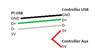