This guide applies to Raspberry Pi 3 B+ and may need some modification if you're using a different setup. The main reason I did this was because my USB-serial on my mega died. Another reason to do this is you might want to put your RPi inside your control box and don't want a bulky USB cable.
Step 1: Make an arduino AVR to program the Mega2560
Refer to https://www.arduino.cc/en/tutorial/arduinoISP
You can ignore this step if you can upload by USB. My original reason for embarking on this was because serial over USB was toasted on my Mega2560. I still needed some way to upload firmware and connect to OctoPrint. Thankfully, I could still upload using Arduino as ISP.
You will need a compatible arduino board. I used an arduino Nano, jumper cables and a 10uF capacitor.
Connect the programmer board - in my case a Nano - via USB. Open Arduino IDE and open the ArduinoISP example File > Examples > 11.ArduinoISP > ArduinoISP. Upload this sketch to the programmer board.
Place a 10uF capacitor on the programmer board between RESET and GND with the negative leg of the capacitor to ground. You may not have to do this step if your programmer board is one of the ones specified in the arduino tutorial. Our programmer is now complete.
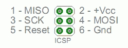
Wire the programmer to the target board (our Mega). I did as follows:
| Pin | Nano (programmer) | Mega (target) |
|---|---|---|
| MISO | D12 | ICSP 1 |
| +Vcc | 5V | ICSP 2 |
| SCK | D13 | ICSP 3 |
| MOSI | D11 | ICSP 4 |
| Reset | D10 | ICSP 5 |
| Ground | GND | ICSP 6 |
Step 2: Configure Repetier to use alternate serial port
Refer to https://forum.repetier.com/discussion/comment/20734/#Comment_20734
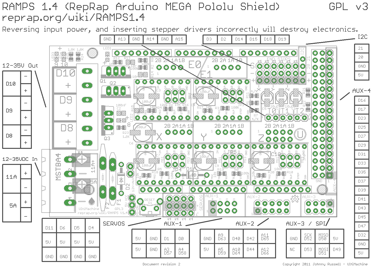
The RAMPS board uses the serial Tx and Rx pins for other things. We need to free up a couple of these pins to communicate with our Raspberry Pi. We also need to let Repetier know to listen to another serial port. This is configured as bluetooth in Repetier. If it’s your first time configuring Repetier, take your time and do your research, because you will need to pull the RAMPS board off the Mega if you get it wrong and upload the firmware again.
I followed this post from the Repetier forums to determine which pins to use. It made the most sense to to me to use Y max as the new Z min pins. I had to change these from normal settings in the Repetier configuration tool:
| Setting | Previous value | New value |
|---|---|---|
| General > BLUETOOTH_SERIAL | No bluetooth connected | Serial 1 |
| Mechanics > Z_MIN_PIN | Z min endstop | Y max endstop |
| Features > Z_PROBE_PIN (if you use a probe) | Z min endstop | Y max endstop |
With the firmware configured, it’s time to upload it to the Mega via our programmer. Make sure it’s wired up to the ICSP pins listed above. Tools->Board should be the mega and Tools->Programmer should be Arduino as ISP. The COM port should be set to the programmer’s. Upload your sketch using Sketch -> Upload Using Programmer.
Step 3: Connecting RAMPS board to Raspberry Pi via UART GPIO
Refer to https://oscarliang.com/raspberry-pi-and-arduino-connected-serial-gpio/
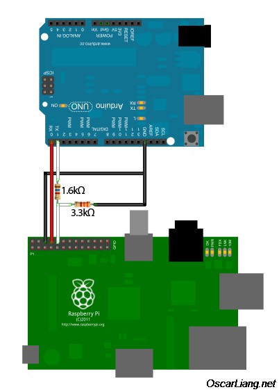
RPi GPIO operates on 3.3v but the Mega2560 is 5v therefore A voltage divider is required from the Tx pin of the arduino to the Rx pin of the Pi to protect it. I followed the referred page to build the circuit. It specifies 1.6k and 3.3k Ohm resistors but I didn't have any on hand. I used this voltage regulator calculator to figure out what other values I could use and ended up using 10k and 20k Ohm resistors. If you have only one type of resistor, you could wire up two in series.
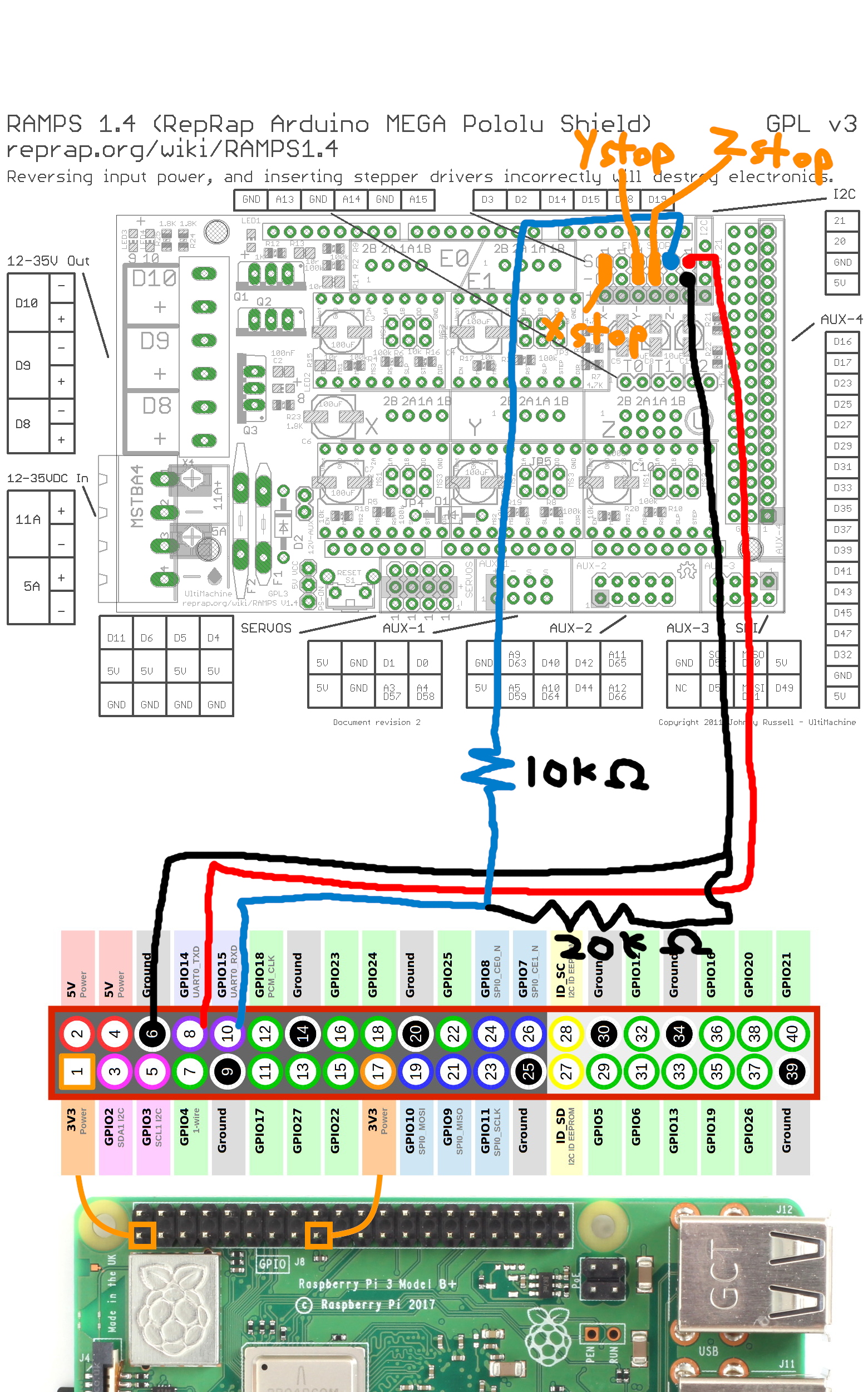
When we're wiring up the RAMPS, I moved the Z min endstop switch one column to the left (refer to this diagram) to where Y max would normally be since it's not used on my printer. We then connect Tx to Z-min, Rx to Z-max and GND to GND (- pin just under Tx or Rx will do).
| RAMPS labled pin | Function | Connect to |
|---|---|---|
| Y+ S | Z endstop signal | Z switch or probe |
| Y+ - | Z endstop ground | Z switch or probe |
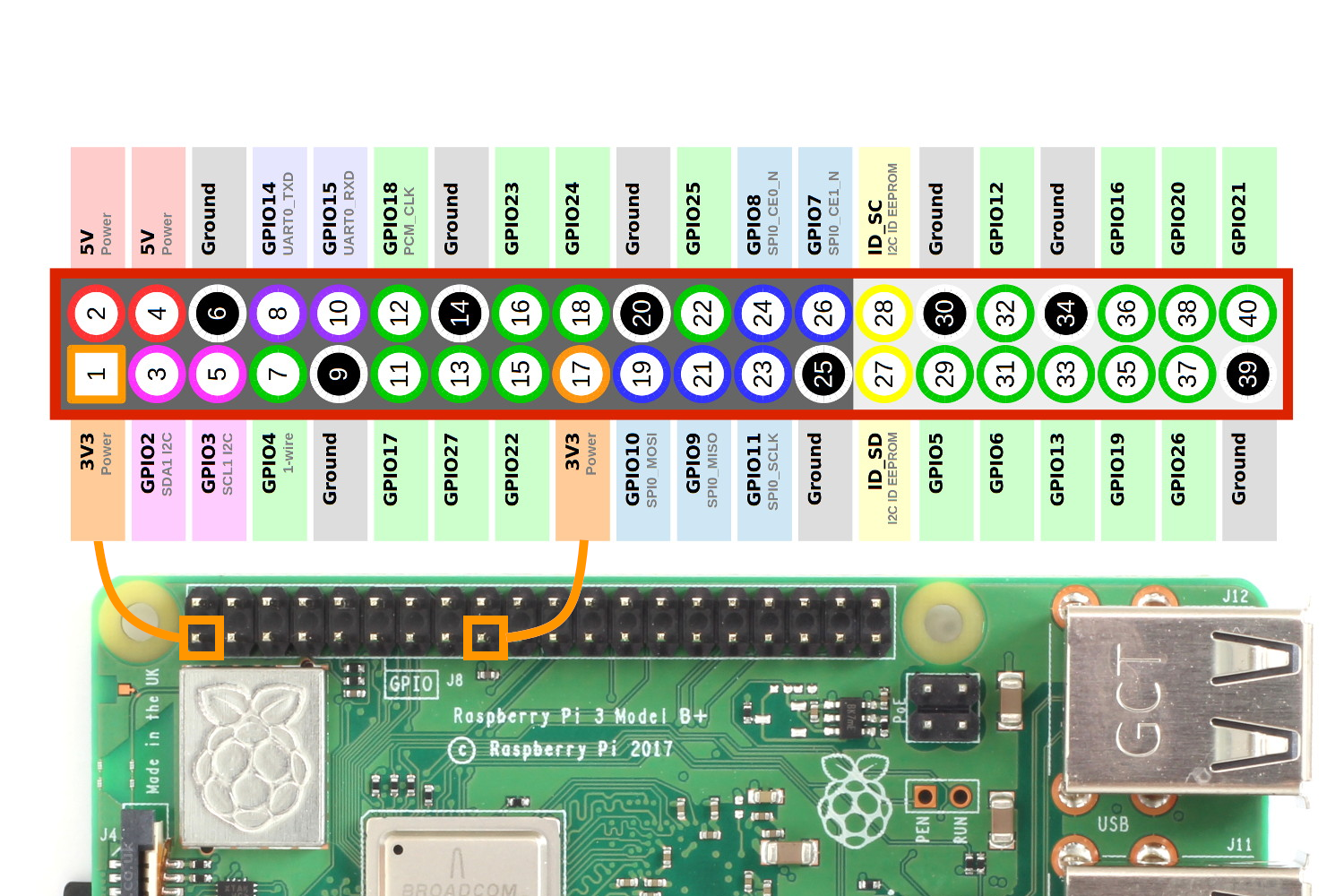
| Z- S | Mega2560 serial 1 Tx | RPi GPIO 15 (UART0_RXD) via voltage divider |
| Z+ S | Mega2560 serial 1 Rx | RPi GPIO 14 (UART0_TXD) |
| Z- - or Z+ - or any GND | Ground | RPi GND e.g. header pin 6 via voltage divider |
Double check the wiring for the voltage divider so you don't blow up your Raspberry Pi.
Step 4: Configure the Raspberry Pi to use UART
Refer to:
We need to configure the Raspberry Pi to stay off the serial pins so we can use it to communicate with OctoPrint.
Do sudo raspi-config and go to Interfacing options > Serial.
-
Would you like a login shell to be accessible over serial? -> No
-
Would you like the serial port hardware to be enabled? -> Yes
Edit /boot/config.txt and add enable_uart=1 and dtoverlay=pi3-disable-bt to the end. This is to disable bluetooth from using UART.
Run sudo systemctl disable hciuart to disable the bluetooth service and reboot.
That's it. Load OctoPrint and you should be able to connect over /dev/ttyAMA0.