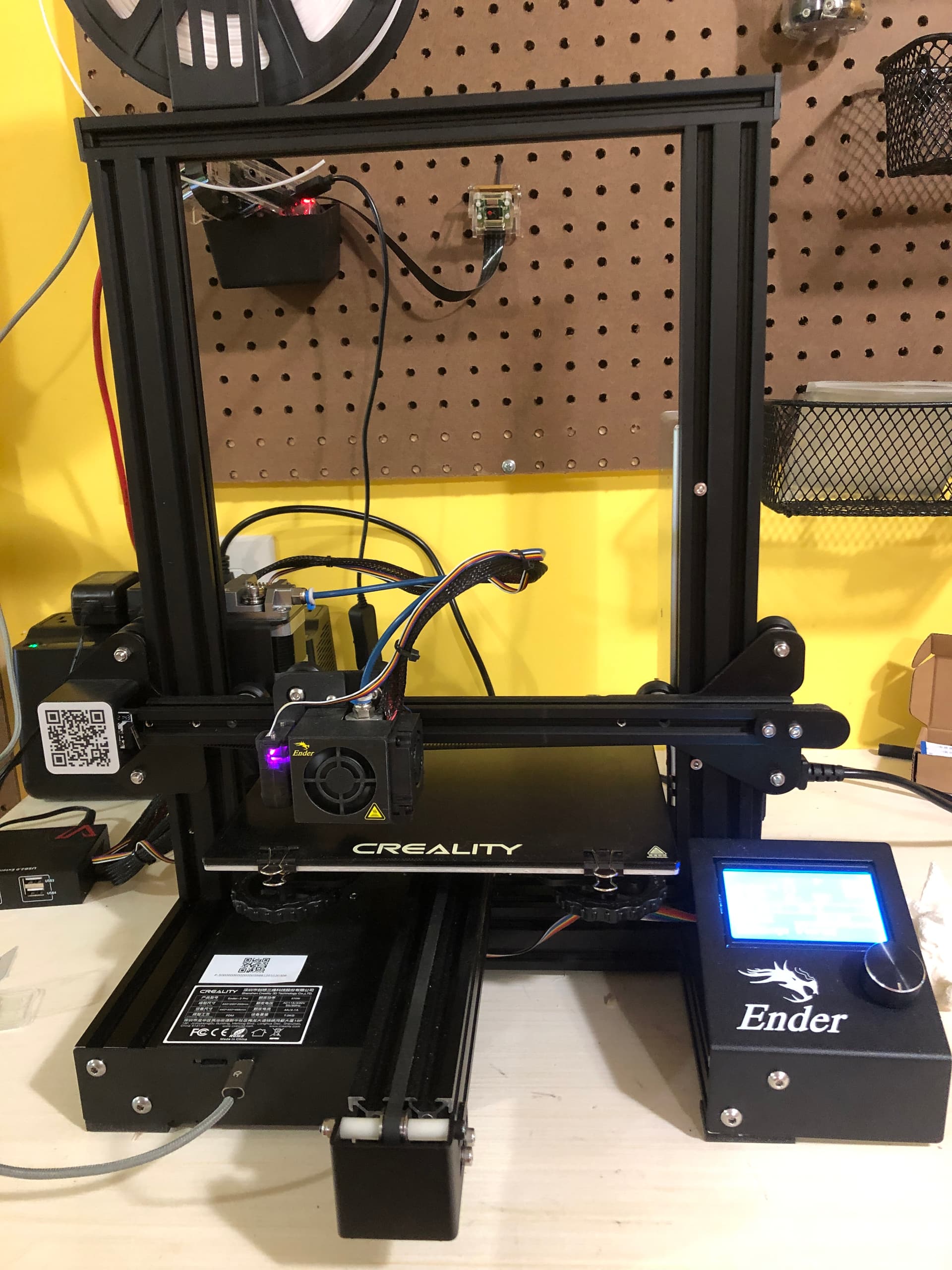
OctoPrint version, OctoPi version, printer, firmware, browser, operating system, ... as much data as possible
I have had a nightmare working with this system. Whenever I've trammed it, I check a few hours later and it needs it again. I've upgraded to heavy springs and to a glass print bed. I spent a month trying to tram and print a test pattern on the bed. I ended up with a clogged nozzle, so I cleaned it, but before I got it printing anything from that, I lost power to the workshop for 6 weeks. So I tried to tram it again - but, suddenly, instead of going to the edge of the print bed for 0 on the X, it was going to the far left, up against the X switch/sensor. (Didn't do that before the outage.)
I used AutoBim, but after about 8 rounds of tramming, suddenly it was reporting my bed was even farther out of alignment than it was when I started. I'm not sure what I should set as a tolerance for leveling and I'm frustrated that, suddenly I seem to need to specify an X offset that I never had to use before.
Also, using the Shiny Upgrade firmware. That's likely going to change, since it's now really tough to get support for it.
Interesting. I did focus on level it all at the start. It's on a DIY table, since I wanted a standing table, not a sitting table. If I want to check how level it is (then work from there), would using a level on the print bed or on the top of the gantry or on the bar that holds the print head be best?
The table itself isn't that important. There are even printers that print upside down
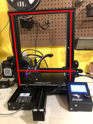
What I meant was that the gantry does not seem to be level compared to the frame of the printer.
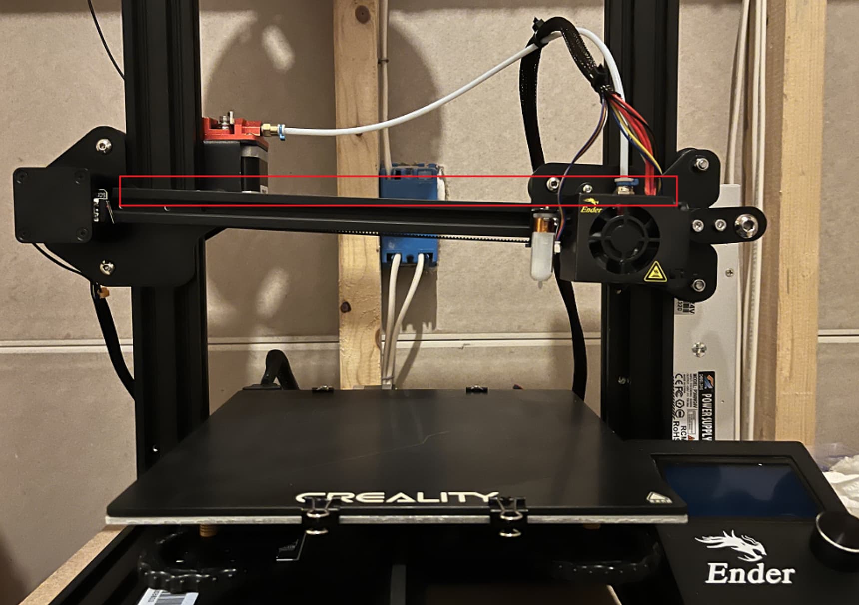
Here's a picture of another Ender - does it look similar on your printer?
It's hard to tell. I don't see anything that far out of line. If it's out of alignment, it's not enough for me to detect visually. I did pull out a level and put it on the top. It's not quite level.
Are you saying it can be a little off on the table itself as long as all the parts are square in relationship to each other?
Yes.
Of course the gantry in the image is an extreme case, but it's a good example on how it shouldn't look.
The problem with a crooked gantry is that bed leveling assumes that the probe is on the same level as the nozzle. Of course there is an height offset (Z axis) between the tip of the probe when it's deployed and the nozzle, but you can easily measure it and the firmware will compensate that for you.
Then there is an offset on the X and Y axis. The firmware assumes that if it probes a point and you move the nozzle to that point that the nozzle height = height - Probe Z offset.
If the gantry is crooked that's not the case.
I can't tell you why you get different readouts every time tho.
Heavy springs sounds good, the stock springs are horrible sometimes.
Personally I would level the bed with the old paper method.
Heat the bed to 60°C, move the nozzle to one corner of the bed (use a ruler so you always got roughly the same distance to the corners), put a piece of paper between nozzle and glass bed, turn the Z axis with your hand until it touches the paper (turn the coupler on the stepper motor), turn on the Z stepper with the M17 Z gcode (so it keeps the height), then adjust the screw so that you feel a slight drag when you move the paper and repeat that for all corners. You might want to check all corners a second time.
It's important to heat the bed up because it might deform a bit when it's on a lower temperature.
After that bed leveling should compensate for all other irregularities of your bed.
Of course you can improve your bed level with plugins like this tramming wizzard or the Bed Visualizer but that should give you a solid base to work with.
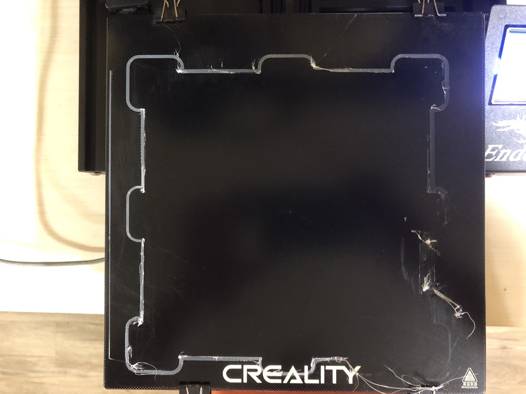
I'm a good ways from stores and supply places (at least an hour, round trip, to get to the closest store and back home). So I did a bit more today. I've replaced my firmware (it was Shiny Upgrades, but now I'm wondering how reliable that one was) and trammed it using the firmware tram wizard, then leveled the bed. This is what I got when I tried to print a test pattern:
(Please note this is after I spent a LONG time tramming it to be sure it was level, then running an ABL on it.)
My first thought is you might be completely on target about how level things are, since the worst issue is on one side, but there are problems on the left side as well. In the past, when I've seen this kind of thing, I've tried adjusting as I printed, but I didn't want to do that today - just wanted one print as a baseline.
Tomorrow or Tuesday I have to make a trip in to pick up a few things. I'm going to go by a building supply store and pick up a package of shams. I'm thinking if I can level the printer, I can then compare the parts by using a level. As it is, when I've tried to use a level, it seems like they're all off center by the same amount.
On the chance that the bar with the printhead is not level, is there a good reference on how to level it?
(Also, does "gantry" refer to just the one cross piece that the printhead rides on, or to the structure?)
I bought shims from Lowe's today and used them to try to level the printer. That's where I started to find issues - frustrating issues.
I'm not sure if the term "gantry" refers to the full structure, made of two uprights and one top horizontal, plus the moveable horizontal, or if it refers to only part of the structure. I'll use the terms "upright" for the two vertical posts, then top for the piece going across the top, and slider for the horizontal bar that can move up and down and on which the printhead moves back and forth.
First, I wanted to put in a shim on the front and back of the left side of the printer, which is the lower side. I took one shim to slide under the front left and I put a level on the top bar. It never got level. Once the shim had lifted the left side a certain amount, the right side went up with it. I could not make the top bar level that way. I know you said the entire printer doesn't need to be fully level, but the only way I think I can make a comparison is by leveling the printer, then checking the other parts to see if they're level or exactly upright. I figured I can always remove the shims later and leave it sitting on the table.
But I could NOT make the top level. I finally manually held down the right side of the printer with the shim on the left adjusted to make the top level. Then I checked the other parts. The left upright was directly vertical. The right one was off and the bubble on the level was significantly more off center than it had been on the vertical before I held down one side. The slider was notably out of level as well.
So my right upright and the slider bar are significantly out of square compared to the top bar and the left upright.
I don't see any way to adjust the right upright - is there one? And the slider bar being out of level would explain to me why there is such a difference between the left and right side of the first layer. I would think adjusting the slider bar is more important than the right upright. What do I need to do to adjust the slider bar?
By the way, the lines you drew on my photo were pretty much on target! If you adjust it so the top bar is level, the left bar will be vertical, the right bar (which leaned to the right) is off and the slider bar is pretty much like it looks when you drew the red line.