I just tried to connect to my Ender 5 with Octoprint on my Raspbery Pi 3 Model B+
Keeps on giving me Error: Failed to autodetect serial port, please set it manually.
There is no other option in the serial port than Auto and I have tried changing to all of the Baudrate and wont work. Tried the USB cable that I have on my Ender 3 that has the same setup and will also not work.
I have the same problem. I would be very happy about a solution. I hope someone can help us.
Same stupid problem...har it working but now it refuses...did you solve it?
new user here, having the same problem.
If the printer is not listed in the drop down its not recognized as a serial interface by the underlying operating system.
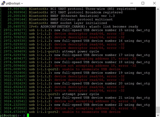
Login via SSH, unplug the printer, plug it back in, run dmesg and share the output.
by " Login via SSH, unplug the printer, plug it back in, run dmesg and share the output." you meen log in at putty f.ex? and then run "sudo dmesg"
Yes 
You can log in anytime but run dmesg after unplugging and plugging the printer back in.
Gets this faults, the serialport1 was set to 2 and serialport2 was set to -1, Baud 250k in Marlin 2.0.x
Try this
I'll try it now  coming back 2 you with the result
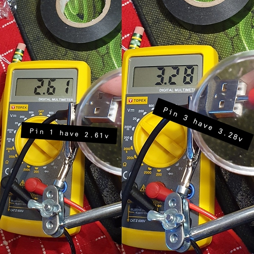
i`ve measured the volt from the pins beacuse nothing happend when connecting the usb, and the result is that pin1 (2.61v) and pin3 (3.28v) have voltage of a total of 5.89volt this ->
Hmmm...
The thread @PrintedWeezl mentioned is about preventing to support the printer logic board with power form the RasPi.
You are measuring the values from the printer.
Pi 3 is a data line. You cannot just add voltage of a data line to power line of the USB cord.
The question for me is: where did you connect the negativ lead of the DMM?
Also: the USB A connector, that is connected to the Pi, gets the power and the B connector, that is connected to the printer, delivers the power.
This seems very iffy to me. The black lead of the multimeter really needs to be on a ground pin on the Raspi rather than something else. I prefer trying to use BOARD pin 39 on the opposite end of the GPIO block since then I don't have to count over from anything; it's just the end pin on the inside opposite the only one with the square marking at the far side.
If you're seeing less than 5V on the VCC pin of the USB cable (as plugged into the Pi) then there's a problem.
Spoiler alert
But since you're showing the Type-A side of the cable then I have to assume that the other end (Type-B) is plugged into your printer board. I'm guessing that PrintedWeezl wanted you to tape the Type-A side VCC pin connector of this cable, to plug it into the Pi and to measure for the absence of 5V on the Type-B side of the cable.

