OK I stop trying then! Thank you!
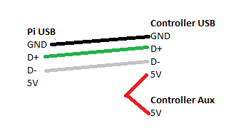
I was having occasional undervotage and other gremlins on my printer, so I was looking for a way to isolate 5V and saw the tape-pin method suggested. Unfortunately, my board would no longer communicate (2560 / Ramps 1.4). Looking at the schematic for the 2560, it uses an ATMEGA8U2 as a USB to UART converter, and on that chip, if the USBVcc is unpowered, it won't power the USB side of the converter. If you don't have 5V on your cable, no USB communications will happen. So give it 5V! But, from your printer's control board, not your Pi  . Most boards should have a ton of 5V pins on aux I/O.
Just made a cable to do this on my printer and it is working great. Time will tell if it solves my undervoltage and other gremlins.
1 Like
One of the designs—on paper—which I created was something like...
- Pi-side relay, if on, allows the Arduino to see its own 5V on that Arduino-side 5V serial pin
- Arduino-side relay, if on, allows the Pi-side relay to have power
So basically, if either side is off then there is no communication. But if both sides are on, the 2nd relay powers the first which then allows the Arduino to see its own 5V. The Pi never sinks power but neither side are fooled into thinking the other is up when it's not.
Perhaps some cleverness with resistors such that the 5v pin was logical Hi but very little current?
1 Like
Possibly. We're mostly concerned with the current-limiting aspect of this.
I think it's not so a good idea to let an IC receiving signals without it's 5V-supply. Although generally all IC-inputs have protector-diodes inside, where the missing (5V-)voltage could surge, it may under circumstances destruct the signal-receiving IC.
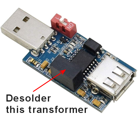
I solved this 5V-isolating-problem with a (magnetic) USB-to-USB-Isolator (including the ADUM4160-IC):
 - available on Amazon, ebay, AliExpress, etc...
I desoldered the (5V-)transformer to split the Power-Lines, so each side is powered from it's own 5V-line.
So if one of the two devices (3D-Printer or RasPi) are OFF, neither signal nor 5V can pass through - all 4 wires are automatically OFF and Printer <=> RasPi communicates only if both devices are "on" - but they are electrically independent from each other.
2 Likes
Sadly it doesnt work on my Prusa Mk3S. I needed to do something as I have had periodic reboots of my printer since I started using a 5v buck converter to power the Pi from the 24v psu and a USB cable to connect the data. If I disconnect the USB it works ok (apart from no communication!)
I dont want to go back to powering the Pi from the Einsy board 5v supply but I may change the data transfer back to the trusty ribbon cable I used before.
@PrintedWeezl
Could that be, if you don't tape the 5V pin, that months of usage like that will eventually kill the serial port on the printer's motherboard?
I have an Ender 3 (not pro) with an mks gen l version 1.0 and through an usb it has been working for months, until yesterday. The serial port on the mks is dead, I know that because I have another one and OctoPrint detects that one.
It wouldn't be nice it that's the case and I go through the hassle of customizing Marlin all over again (I lost my backup of it) and then this will just happen again after a few months.
The Pi is directly powered with a buck converter connected to the PSU so it power up at the same time as the printer but the printer reboots after a few seconds because, I think, OctoPrint takes longer to power up an make the mks reboot when it does.
@8FootedAlgaeEater
How has this been working for you so far? Any problems?
I'm almost an electrician so I could very well do this. Bypassing the serial port of the mks could save me a lot of time having to do all the programming again with a new board. But if this method comes with some troubles, then maybe it's not worth it.
This is expected behaviour on many consumer/hobby 3D printers. What is probably happening is it takes time for the Pi's OS to spool up and then launch the OctoPrint process. You must have OctoPrint configured to automatically connect, it is this connecting (opening the serial port) that causes the printer to reboot.
The reason for this is when the printer boots it waits for signalling from a firmware update program (avrdude for the 8-bit AVR chips). If it doesn't see that signalling within a second or two it will then run the last loaded firmware. This is how the Arduino ecosystem does firmware updates, and most of our consumer 3D printers (particularly the rep-rap based printers) are specialized Arduino appliances.
1 Like
not that I'm aware of
1 Like
It hasn't been said here but turning of the power to the RPi without a proper shutdown has a non-zero probability of corrupting the RPi SD card. The RPi doesn't consume much power and having it on even when the printer is off can be very useful.
2 Likes
I tried this and it does not work.
Initially I saw this and it seems to make sense. Then I realize that ADUM4160 also need power supply on the downstream side (printer) but you are not suppose to use the downstream 5V, and Ender 3 indeed does not supply 5V to micro-USB side which makes sense since you cannot connect two 5V together in normal case. Once you removed the isolated DC-DC converter (BTW it is not a transformer) the downstream side is completely powered down and disconnect the printer from RPi.
@coldfire0200: Surely both sides need 5V-Power! And yes, I powered the downside from my 3d-printers 5V-source (normally a cheap 7805-IC or, and on expensiver boards a DC-DC-Buck-converter (from 12V...24V) to +5V. So it's no problem to find out a pin from your printers board powered with his +5V-line and solder a small cable to the USB-plus-Pin, respective the ADUM's +Vbus1 (Pin-1) or Vbus2 (Pin-16) side. Anyhow the two +5V lines have to be completely independent (=isolated) from each-other, so no matter what the original Isolator was(? B0505S datasheet), both sides have to be powered with +5V beeing completely isolated, as well as each pair of USB-Data-lines as the two +5V lines, to get Serial-Connection between RPi and Printer!
It's also possible to add a separate 5V-Supply to the Printers USB-Side (if the USB-Port isn't powered by the printer itself), so adding f.ex. a LM1117-5V Regulator-IC (or a separate 5V Power-Supply) does the job.
And yes: you can connect two lines of 5V together without damaging anything, assuming both sides have nearly the same voltage-levels between 5,00 to 5,1x Volts, but in this case it's safer to separate them, because the printer often has more 5V-consuming-Amperage as the RPi's Power-source can provide (mostly 2-3A) or viceversa... So if one side can't provide them, the 5V-voltage drops down until one of both sides main-IC's /controllers (hardware-)"watchdogs" shut's down (=resets)...
But as @Sembazuru said, this behavior is not here the case but the late "handshake" from Octoprint, trying to connect the waiting Printer. This is normal and no matter to worry about. You have only to wait after Octoprint is ready with its connection to the printer...
@b-morgan: I made a RPI-Hardware "Save-Power-Shutdown" – you may download it (eagle-files, incl. Excellon-file & Toner-Direct-Print-Out) from my homepage, so corrupting the RPi's SD-card is more unlikely.
I made both hardware-solutions presented here and both are working fine since about mid-2020.
@Andri_Mar: If the Serial-line of your printer-board is dead I would try to desolder and change-out the Serial IC (mostly a CH340C) with 350°C hot-air. So you may save your board - if no other IC is "dead"... and if successful, I would then try to save at least the .hex-file from the board's controller, so you have at least a "hardware"-backup for a hopefully not next time, but sadly not the possibility to modify any lost marlin-files further... Try this (on a command-line in the avrdude-folder):
avrdude -patmega2560 -carduino -P [COM-PORT] -b115200 -U flash:r:"flash.hex":r
where you have to find-out your serial-Port, replacing here the named [COM-PORT], on Linux usually /dev/ttyUSB0 and on a PC usually "COM2" to "COMXX".
Your backup then is the "flash.hex" file.
This tape solution does not work for my Ender 3 Pro. Wish I had known about this issue before spending money on the Pi and it's peripherals.
You know, it would be a lot easier to just cut the 5v wire...
Was just wondering when I had to wire in the USB connecter to the mother board of the Qidi X plus which is very easy to do. The Guy in the youtube video said not to connect the 5V DuPont connecter on the mother board side maybe this was to stop some problems like this happening in the first place. Glad I did not connect it now. my best Daz
worked very well on my Ender 3v2 printer
2 Likes
electrician here, your good with masking tape, painters tape or even some scotch tape. The only problem is if it will stick once you slide in the usb cord. I wouldn't use duct tape since you could have a possibility the glue from the tape getting all over the inside of the usb jack. electrical tape is the best and only about 99 cents a roll, also good for future projects. you can even find the stuff at the grocery store
4 Likes
I forgot to fit
a back to back USB plug-socket assembly like this 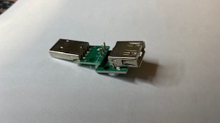 which I use routinely for all Pi-Printer connections. The assembly disconnects the +5V rail from whatever the Pi USB is connected to - this was on a CR10SPro mini USB port - there was sufficient power to keep a Raspberry Pi4 alive. Its a bit confusing when you KNOW its shutdown, but the network RJ45 port leds on the Pi are still lit.
Not pretty, I should make cases for them, but they work..
Same thing here:
Since using a webcam with octoprint the message about under voltage is coming up.
Does the cut out 5V work with an Anycubic Mega S too?
Thx in advance
EDIT: it works, but the undervoltage message is still there, I´ll try another power supply and report here again
EDIT2:
After taping the 5V pin and rebooting the complete system (Raspberry Pi with Octoprint) it works fine. I´ll have a look for another power supply, but actually it seems to run without failure messages.
EDIT3: After 6 hours of printing there no message of undervoltage, but then after about a further hour while not printing the message is there again. I don´t know why, but another power supply is definitly needed!
EDIT4: I took another USB-cable and cut out the 5V-pin within the cable itself. Then I took a 5,1V 3A power supply which is now tested. I´ll report again....
2 Likes